SlimeVR Documentation
Welcome to the SlimeVR documentation. This site covers how to build your own SlimeVR trackers, install or update an existing tracker's firmware, install and configure the SlimeVR Server, and provides a wide collection of community built tools.
What is SlimeVR?
SlimeVR is a set of open-source software and hardware sensors designed to facilitate full-body tracking (FBT) in virtual reality. The project is built around the core concept of creating a system that can be fully customized to suit each user’s needs. This documentation provides a full breakdown of how to set up prebuilt trackers, as well as guides on building compatible DIY SlimeVR Trackers. For a more detailed explanation of how SlimeVR works, check SlimeVR 101.
I have prebuilt trackers, what do I do now?
Welcome new SlimeVR user, we're happy to have you here! For the simplest setup process we suggest you visit our Quick Setup Guide.
How do I get my hands on those sweet sweet SlimeVR trackers?
There are currently multiple ways to approach putting together your own SlimeVR FBT solution.
A minimum of 5 SlimeVR trackers is required for proper full-body tracking (FBT). Alternatively, you may purchase or build a single tracker exclusively for chest tracking if you want to test partial tracking without investing in a full kit. Other options, such as using phones or Joy-Cons — do exist, but tracking quality is heavily restricted by the specific device—so expect significantly worse results.
1. Buying trackers
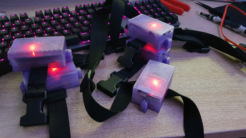
Fully built trackers directly from SlimeVR
![]()
Fully built trackers are available for pre-order at Crowd Supply. These trackers are a passion project of the dedicated core members of SlimeVR, and due to chip shortages, shipping delays and the like we cannot guarantee shipping dates or turnaround time.
This option is a pre-order. Please check the product page for estimated shipping times for new orders. Actual shipping times might differ due to production delays and other circumstances.
2. Third-Party Sellers
Third-party sellers are common, with prebuilt trackers and custom commissions offered on the SlimeVR Discord marketplace forum. Designs and specifications vary from seller to seller, so make sure to check exactly what you’re getting.
As the two most important aspects of every SlimeVR Trackers are the IMU (used to measure movement) and the communication protocol (how the tracker communicates with your device), we suggest checking the IMU comparison page to get an idea of what to expect from any available tracker.
SlimeVR cannot ensure that non-marketplace, third-party trackers trackers meet any specific quality requirements. Please assume that purchasing from a third-party seller is comparable to buying from a small creator, and your own research into the quality of these trackers is important. We suggest checking reviews or speaking with others who have purchased from the seller. If any of your third-party trackers develop a fault, contact the seller for support. However, you may need some understanding of soldering and tracker assembly to perform repairs yourself.
Note: You need at least 5 trackers for proper full-body tracking (FBT). Alternatively, you may build or purchase a single tracker exclusively for chest tracking if you want to test partial tracking without investing in a full kit. Other options—such as using phones or Joy-Cons—do exist, but tracking quality is heavily restricted by the specific device, so expect significantly worse results.
3. Building trackers yourself
Entirely from scratch
Example build by NightyIceC00kie
Building trackers is currently the cheapest method of obtaining SlimeVR trackers at the time of writing. This documentation provides a full guide to building trackers from scratch, which provides lists of full components needed, where to buy them and schematics for most combinations of IMUs and Microcontrollers.
The most common way of assembling SlimeVR Trackers is by soldering multiple PCBs onto a carrier board.
- For Wi-Fi-based Trackers ("big" or "normal" Trackers), the component and assembly guide can be viewed here.
- For nRF (“Smol”) Trackers, the component and assembly guide can be viewed here.
PCB-based builds are also frequently used, which can be manufactured through JLCPCB or other suppliers at low cost. These boards can greatly simplify the process and reduce the amount of soldering required. Many popular options are available, with instructions and 3D printable files:community cases
DIY builds require time to assemble and may require self-repairs from time to time.
Please note: If you are looking for the ICM-45686 (the recommended IMU), the SlimeVR store has modules available.
Purchase the official DIY Kit on Crowd Supply
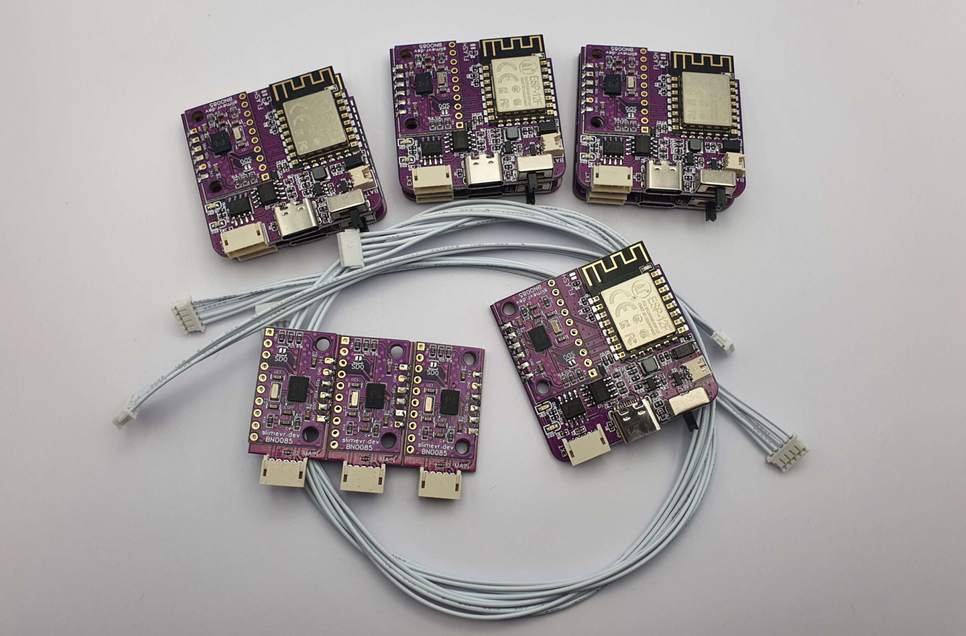
A prototype of DIY-Kit boards and wires.
You buy the official DIY Kit, which includes the boards, extensions, and cables. It does not include enclosures, straps, batteries, or other accessories, which must be sourced separately. See the DIY Kit Guide for more information.
This option requires little to no soldering, provides tested boards, uses the best available IMUs, allows for a compact design, and is a more affordable alternative to completed SlimeVR trackers. It also allows you to customize cases and straps.
Example: TinyOfficial-Case
However, while the cost is significantly lower, this option is still a pre-order. We recommend buying batteries and other required parts at the same time to avoid delays.
Please check the product page and Discord for estimated shipping times. Actual shipping times may vary due to production delays and other circumstances.
4. Alternative tracking options
As SlimeVR is open source and has roots in the idea of experimentation and exploration, other options to replace custom built trackers have emerged. This includes:
- Using a phone in place of a tracker.
- Using Nintendo Joycons in place of trackers.
- Using Mocopi trackers with SlimeVR server
- Using HaritoraX trackers with SlimeVR server
Please note that these options may be subpar when compared to actual SlimeVR trackers, but are useful for experimenting and in some cases can work well. We suggest you do not invest heavily in buying old phones or joycons, as most users of these options only consider them stopgaps at best.
Note that these options vary depending on make and model (for example, third-party Joy-Cons almost never work). Users commonly experience issues with connection stability, application crashes, and other limitations. Phone or Joy-Con straps must also be sourced based on the object’s shape, size, and mounting location.
If you have any problems, feel free to reach out on the SlimeVR discord.
Written by adigyran and calliepepper; edited by QuantumRed#0001, calliepepper, Spazzwan emojikage, nwbx01, and tomyum3dp; styled by calliepepper. Reformatted and rewritten by Amebun to meet December 2025 standards.
SlimeVR 101
What is SlimeVR?
SlimeVR is an affordable solution for full-body tracking in virtual reality. It uses forward kinematics1 to create a model of your body by calculating the position of each tracker based on its rotation. The only fixed point is your headset, which serves as the primary reference position.
Since the headset is the only fixed data point, SlimeVR doesn’t need extra tracking equipment like lighthouses. It relies on Inertial Measurement Units (IMUs) to track the rotation of each device. The more IMUs used, the more tracking points are available for your body.
SlimeVR Compatibility
A very common question we get is: "Is SlimeVR compatible with my hardware?" In short, SlimeVR is compatible with any headset that connects to SteamVR, as well as any headset that can run VRChat standalone. SlimeVR also supports the use of other trackers and estimation software through its own sensor fusion system. You can find a more detailed and comprehensive compatibility list here.
How Many Trackers Do You Need?
Each tracker measures the rotation of a bone, and when the data from all the bones is combined, it creates a simulation of your physical poses and movements. For this reason, you should aim to use enough trackers to meet your specific Full Body Tracking needs.
Depending on how you plan to use FBT in VR, choose one of the following options:
| Set Variant | IMUs | Additional Trackers Compared to Previous Set | Expected Audience | Benefits |
|---|---|---|---|---|
| Lower-Body Set | 5 | Spine, Knees, Ankles | Casual VR users | Provides positional tracking for legs and spine. Limited tracking for foot orientation and lower spine bending. |
| Core Set | 6 | + Extra Spine Tracker | Users who want hip rotation and increases accuracy for torso movement | Adds an extra spine tracker on the hip for improved stability, especially when sitting, lying down, or bending over. |
| Enhanced Core Set | 8 | + Feet Orientation (Extra Feet Trackers) | Users who sit or lie down often | Adds foot movement tracking for more expressive, emotive poses when seated or lying down. |
| Full-Body Set | 10 | + Elbows | Dancers, role-players, immersive users | Enables independent elbow movement, providing more realistic upper-body motion and increased immersion in VR. |
| Deluxe Tracker Set | 16 | Fully Customizable | Motion capture professionals, animators | Can be used for motion capture without VR gear, split into two Enhanced Core Sets, or customized as needed for flexibility and precision. |
For more visuals on what these tracking options look like, watch this video:
What is an Extension?
An extension is a singular auxiliary IMU attached to a primary tracker and placed at another location. This allows you to build a secondary tracker without the need for an extra battery, a charge board, and a microcontroller. These are sometimes referred to as AUX trackers (auxiliary trackers).
Extensions make it possible to track areas with two bend points close together, like the lower leg and foot, without needing another tracker that requires separate charging and communication.
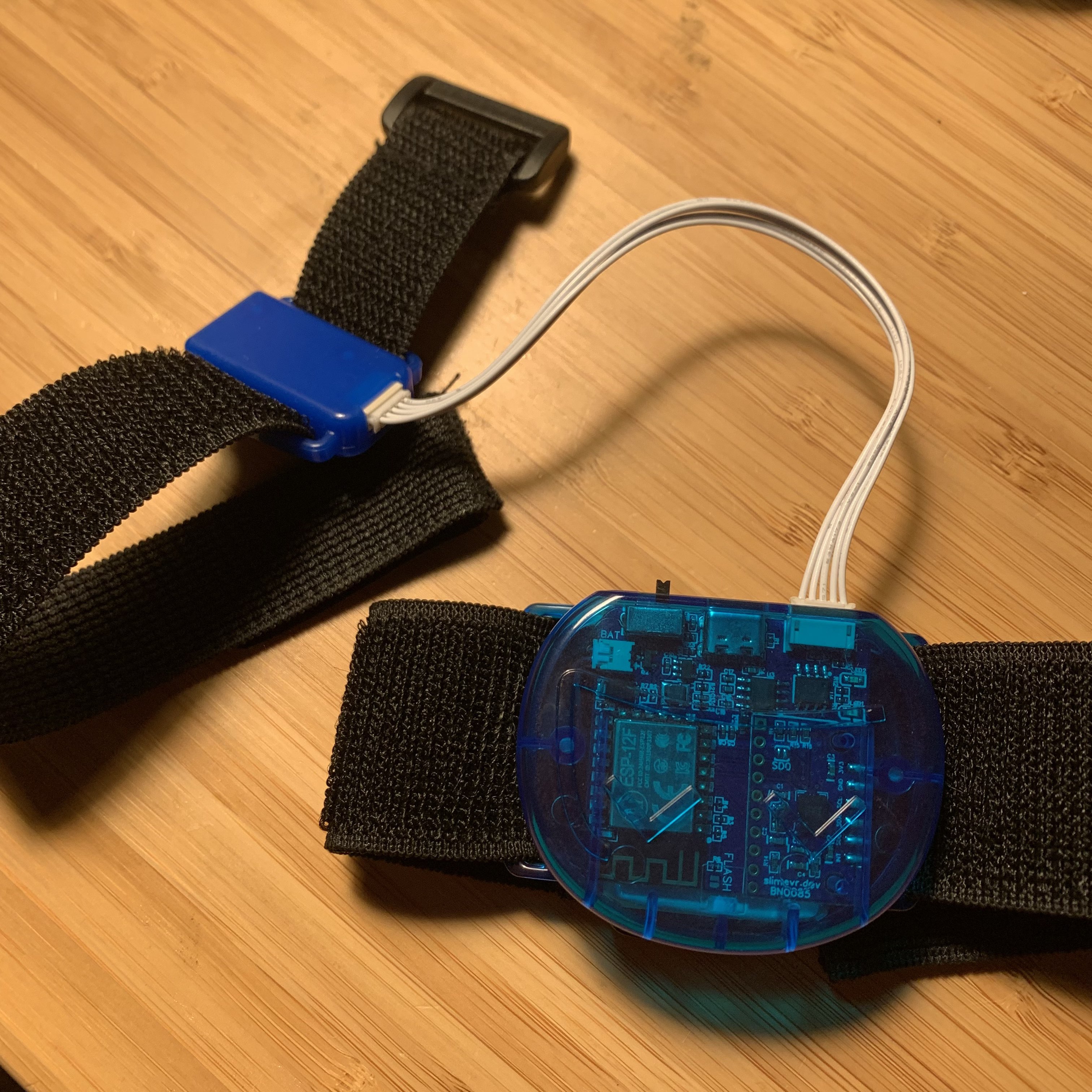
Devkit picture by erimel
The length of the extension is dependent on the cabling used to connect them (shorter than 80cm is a safe range). For more information please check the tracker schematics page.
The suggested extension locations are:
- A hip extension attached to the chest tracker.
- A left foot extension attached to the left ankle tracker.
- A right foot extension attached to the right ankle tracker.
On the Crowd Supply store page and our Discord server, you may find a notation that specifies the number of primary and auxiliary IMUs with a plus sign. For example, the Enhanced Core Set noted above would be called a 6+2 set up, which consists of 6 microcontrollers and 8 IMUs. For a better visual on how this looks when on a person, please check the recommended mounting points section of the server set up.
Please note: Building extensions is not necessary, as the feet and hip locations can be provided by standalone trackers if you prefer. However, these docs assume that you are building them as extensions.
Created by calliepepper. Edited by Amebun, spazzwan and Depact. Video created by zrock35.
-
Forward kinematics is the process of calculating the position of a body part (like a foot or arm) based on the angles of the bones. Given how your joints (like knee or elbow) are positioned, forward kinematics tells you where your foot or arm will be in space. It's like figuring out where your foot will go when you bend your leg a certain way. ↩
Quick Setup
This guide should help you with setting up prebuilt Slime trackers as fast as possible. If you are using phones, DIY trackers or substituting some body locations with anything not prebuilt there are added complications.
Table Of Contents
- Making sure your system is ready
- Install the latest SlimeVR Installer
- Connecting and preparing your trackers
- Choosing and assigning body locations
- Reset Tutorial
- Configuring Proportions
- Final settings
- Enabling trackers on SteamVR
- Congratulations, your Slime trackers should now be set up!
Making sure your system is ready
If you are intending to use SteamVR with your slimes, make sure it is installed and run it at least once before moving forward.
Install the latest SlimeVR Installer
The latest SlimeVR Installer can be found here. Download it and install it, this installer can be used to update the server software in the future.
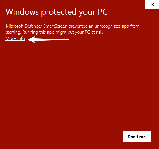
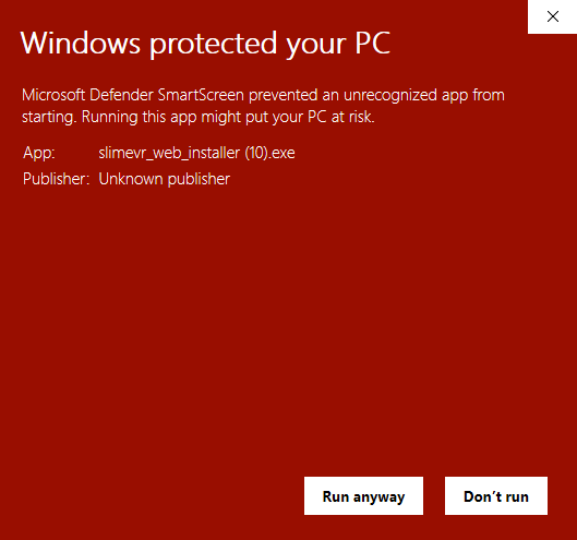
If you are on Windows and encounter the following pop up, click More info text to show the run button. Once it is visible, click Run anyway to progress.
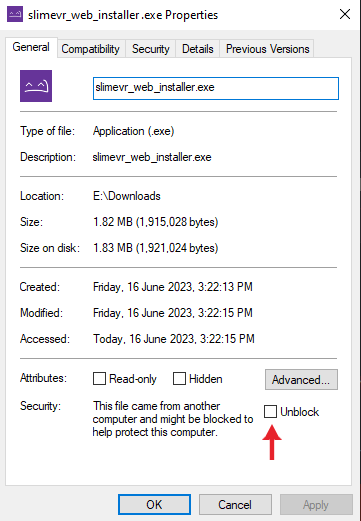
If this doesn't solve your issues, try unblocking the file via right clicking on it, properties, and then ticking the Unblock checkbox.
Once you have the installer launched, click Next > to move through the process. Be sure not to change the pre-checked install packages for use with SteamVR.
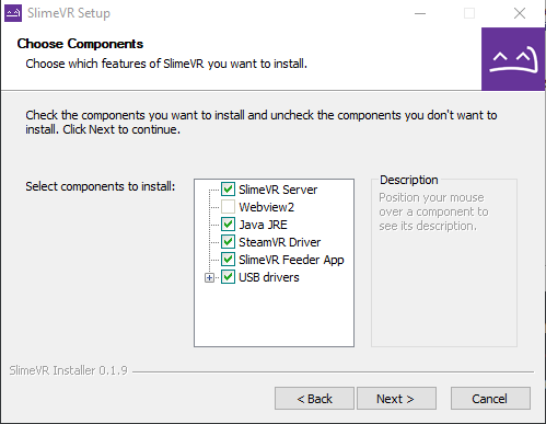
Bear in mind, if you plan on using the server purely for standalone usage via OSC, and not PC VR via SteamVR, you can de-select SteamVR Driver, SlimeVR Feeder App, and USB drivers. If you don't already have SteamVR installed and have launched it previously, you may encounter an error.
Connecting and preparing your trackers
Video Guide
Text Guide
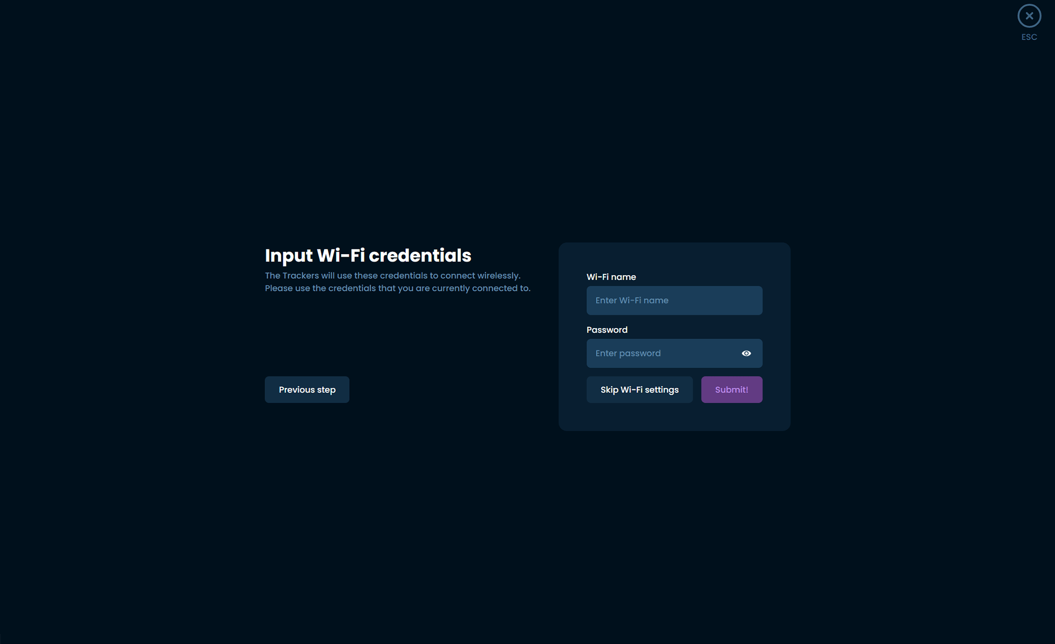
Be aware that SlimeVR tracker will only connect to 2.4GHz band WiFi networks and your host (pc or phone) need to be connected to the same network.
-
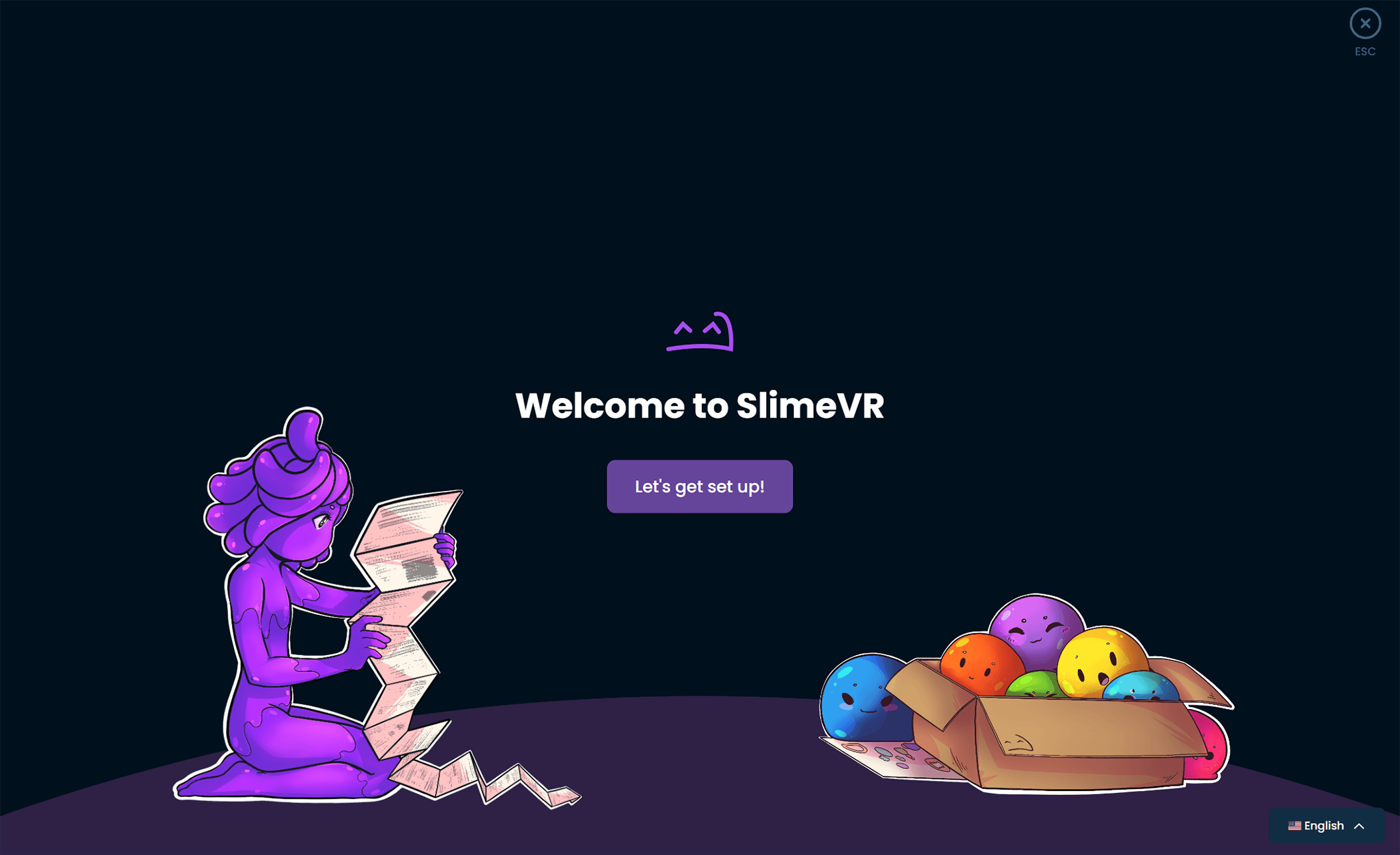
Open the SlimeVR Server. On this first page you can change the applications language via the button on the bottom right. Once you are ready click Let's get set up!
-
Input your 2.4GHz Wi-Fi credentials, so that your tracker can connect to Wi-Fi, then click Submit.
-
Plug your trackers in one at a time and turn them on, you should see the progress bar on the left update to show the Wi-Fi details being sent. Make sure you use the cable included with your trackers, as other cables may not be suited to send data.
-
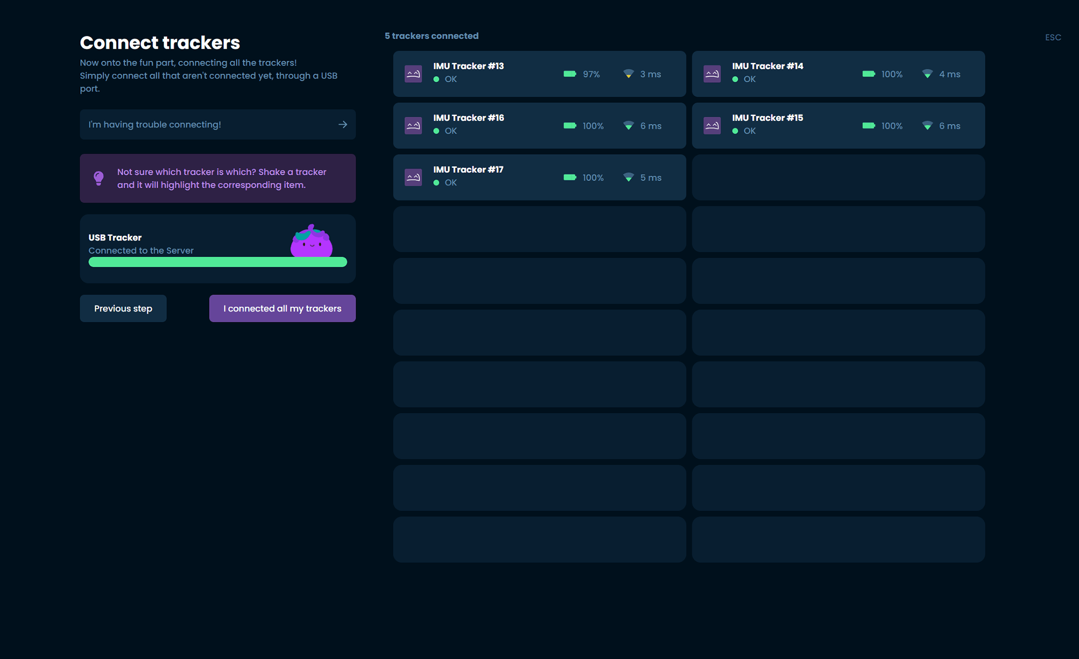
Once you have connected all your trackers, you should see them listed with numbers on the right. If you have forgotten which trackers have yet to be plugged in, shaking a connected tracker will highlight it in the list. Click I connected all my trackers once you are finished.
-
Following the directions shown on the page, place your trackers on a flat surface while powered on and click I placed my trackers on the table before waiting for the process to complete.
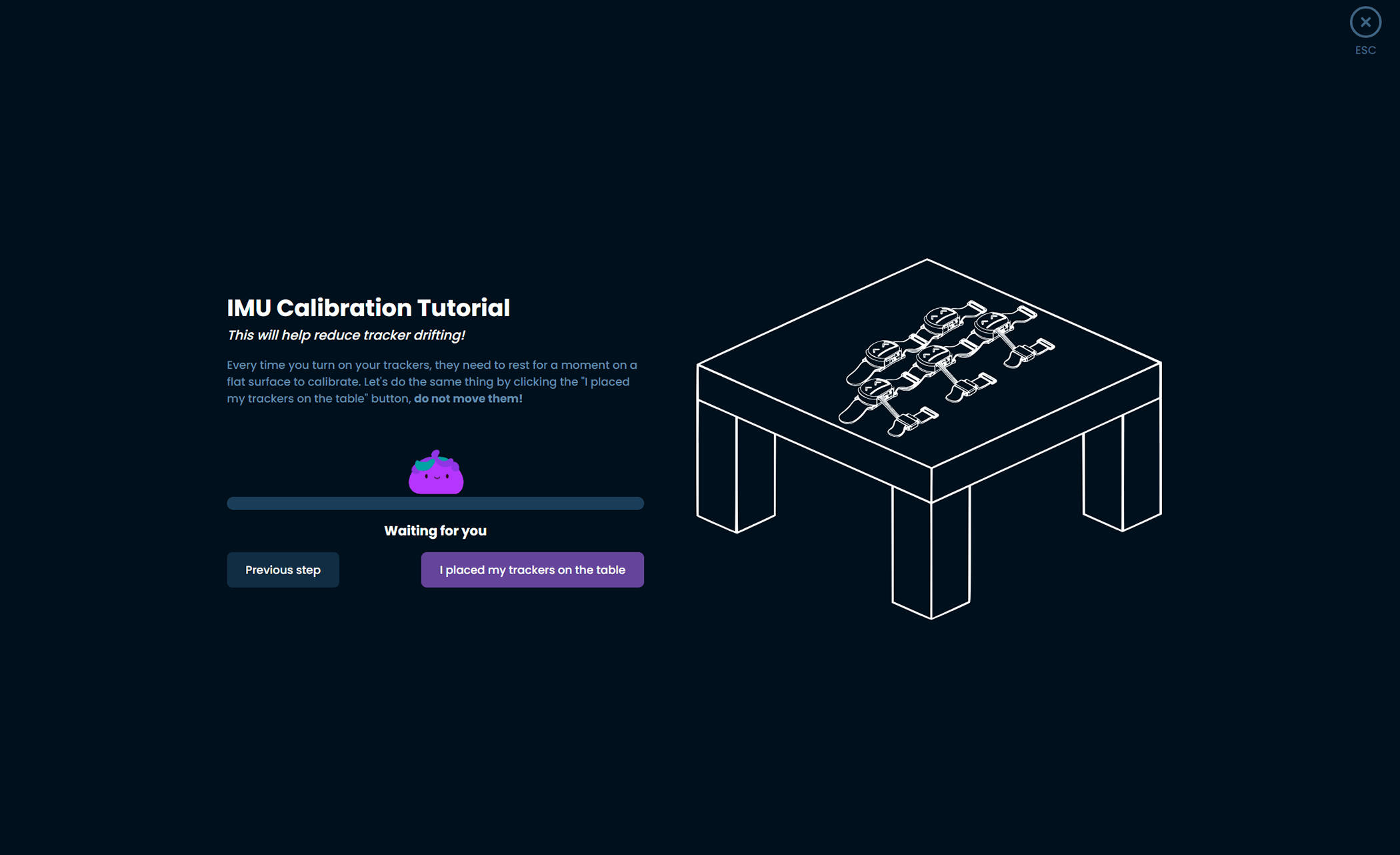
Please note: Each time you turn your trackers on, they will need to perform this calibration. Make sure to leave them on a flat surface after turning them on each time you want to use your trackers!
-
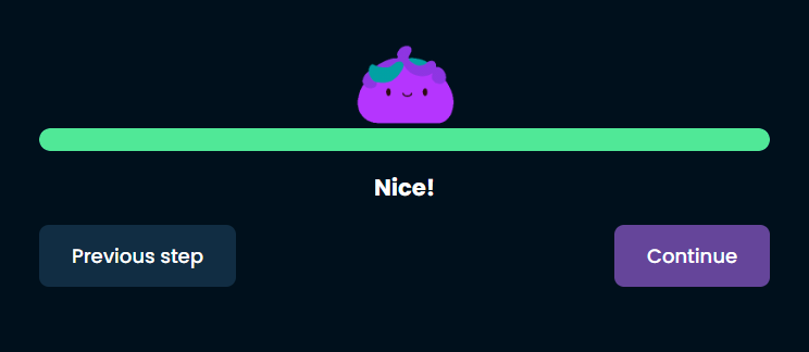
Once calibration is complete, click Continue to continue.
-
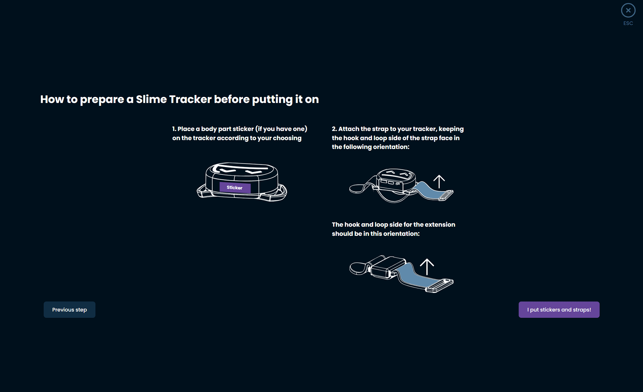
Following the directions shown on the page, prepare your trackers by attaching straps and decorating them with stickers to help you remember which tracker is set up for each body part. Once all your trackers are prepared, click I put stickers and straps! to move forward.
Choosing and assigning body locations
-
Figure out which body parts you will need to assign. Depending on how many trackers you have these are the suggested locations:
- Lower-Body Set (5 trackers) - Chest, both thighs, both ankles.
- Core Set (5 trackers with one extension) - Chest and hip/waist (via the tracker with an extension), both thighs, both ankles.
- Enhanced Core Set (5 trackers with three extensions) - Chest and hip/waist (via trackers with extension), both thighs, both ankles and feet (via trackers with extensions).
- Full-Body Set (7 trackers with three extensions) - Both upper arms, chest and hip/waist (via trackers with extension), both thighs, both ankles and feet (via trackers with extensions).
-
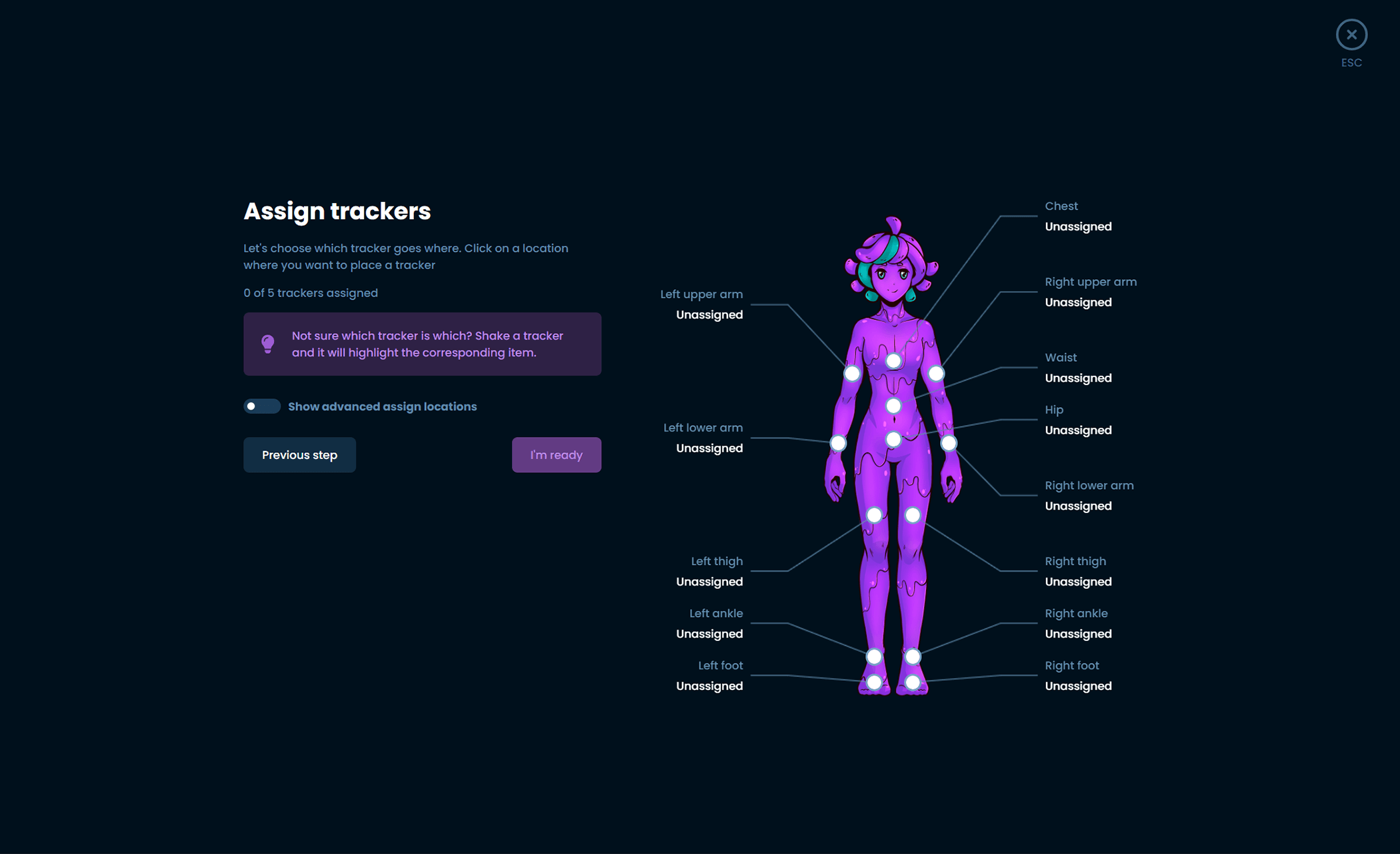
Using this list choose the location on SlimeVR's mascot, Nighty, that corresponds with the area you wish to choose a tracker for.
-
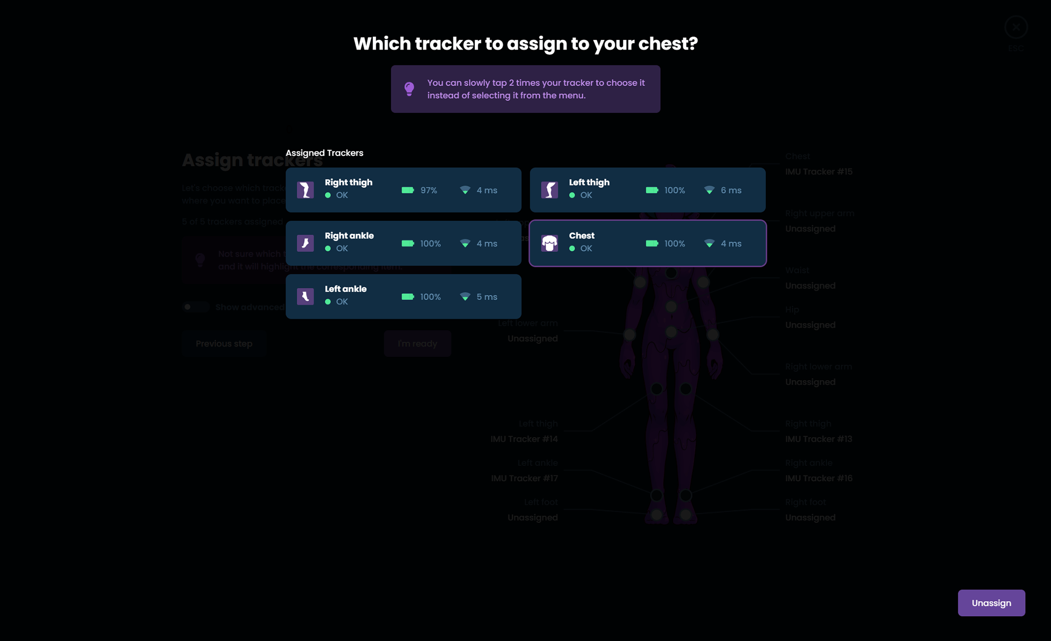
While the pop up is open, you can tap the tracker you wish to use for that location twice to automatically assign it. You can also choose the specific tracker in the list you wish to assign if you find that easier.
-
Once you have assigned all your trackers, click I'm ready to move forward.
-
Take a moment to put all of your trackers on. You can wear them on the front, back or either side of your body at the location marked, taking note of the following suggestions:
- Heavily muscular areas tend to deform easily and can throw off tracking, try to find a position that minimises this.
- The diagram of Nighty should give you a rough area for where to wear them, but you can rotate the position around your body. For example, the chest tracker could be more comfortable on the front or back depending on clothing and body shapes.
- Make sure your trackers are at a cardinal direction from you, they must be facing front, back, left or right.
- Make sure your trackers are the right way up, the Slime's face should upright with the flat part of the tracker facing towards the floor.
- Once you have the tracker on, try moving around and see if they sit still during movement. Some areas (such as ankles) work a lot better on the side of the ankle instead of the front.
- All bodies are different! Mounting orientations that work for others might not work for you, and you might need to experiment to find the best place for you.
Once you have your trackers on, hit I'm ready to move to the next step.
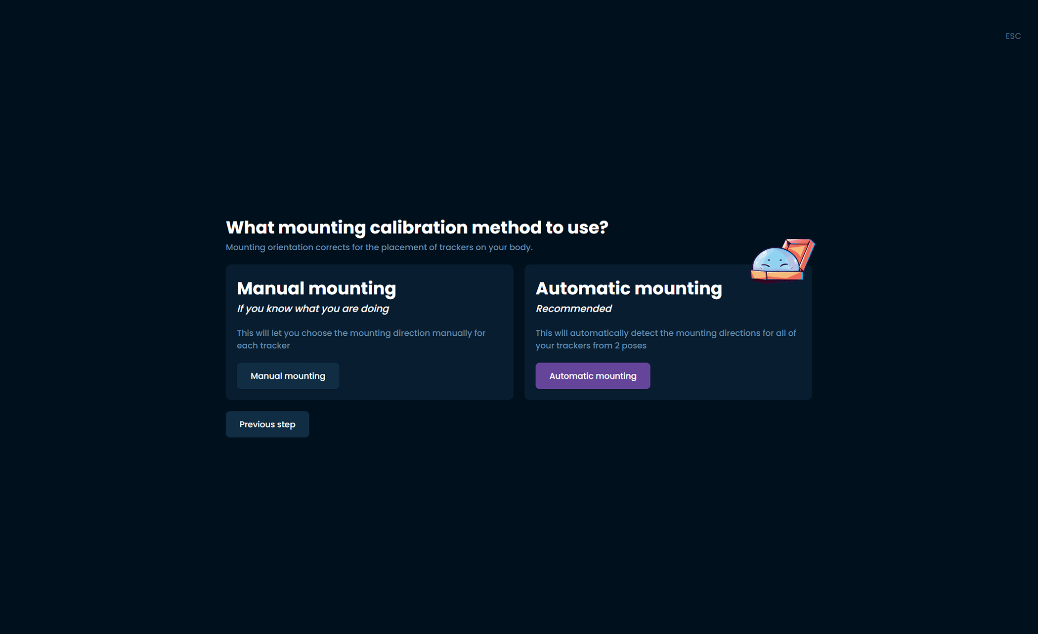
-
SlimeVR offers an automatic and manual process for determining mounting orientation, automatic calibration can lead to better tracking quality, but improper calibration can make it worse. It requires some time to figure out and check if it's right for you and the way you put on your trackers. We're working on making it better, but we suggest new users use the manual process.
-
Click on one of your trackers to bring up a list of mounting orientations.
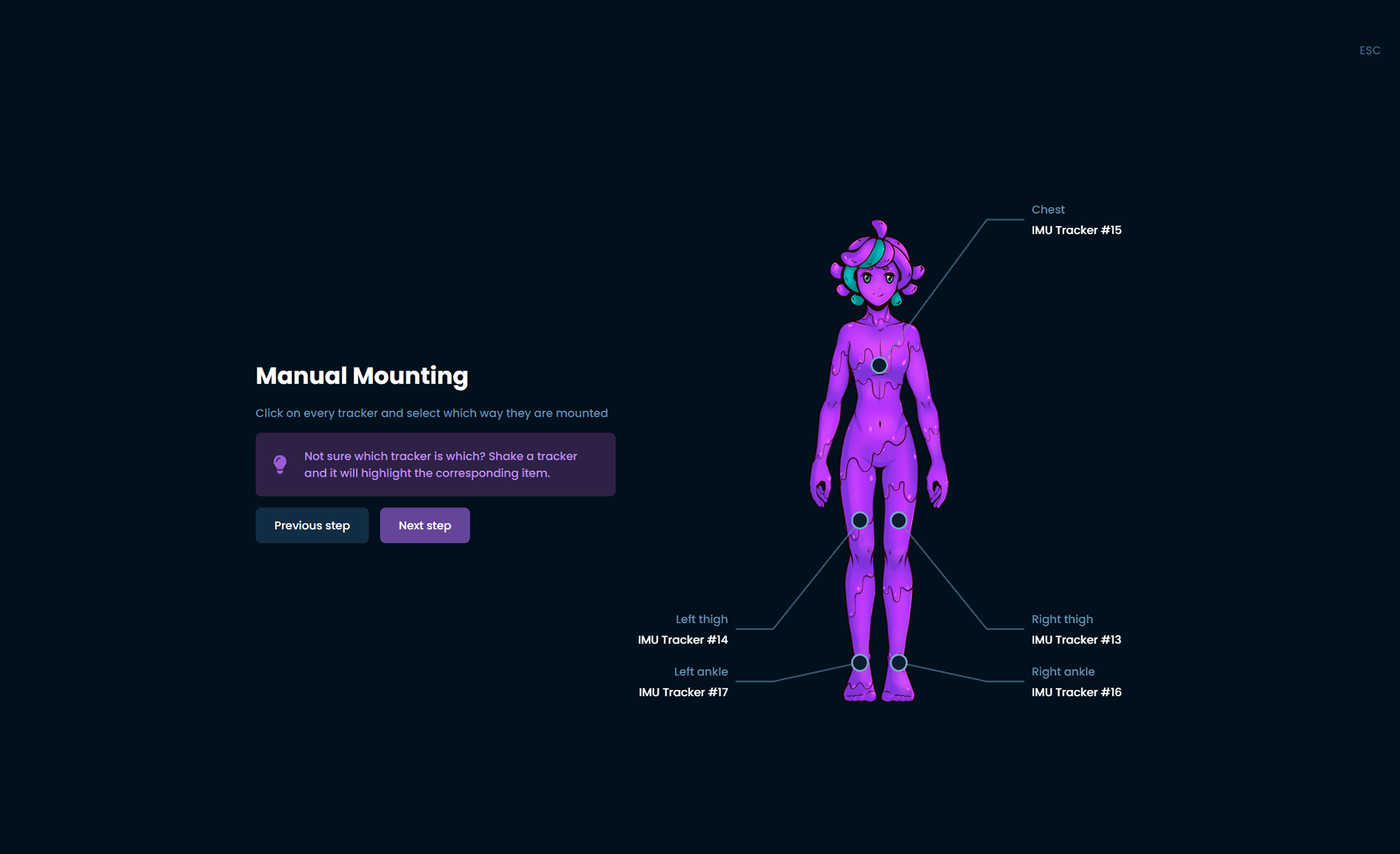
-
Choose the orientation that best represents the mounting orientation of that tracker.
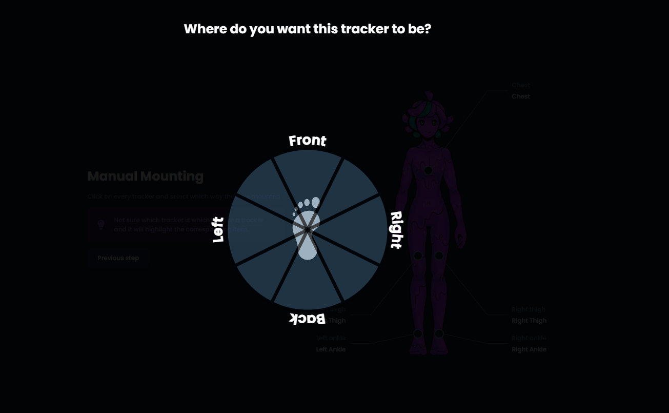
-
Repeat for each of your trackers, when you have completed this process click Next step.
Automatically setting mounting
SlimeVR offers an automated process for recording which mounting orientation you have set up with your trackers, which can lead to issues for new users but for experienced users can give better results. Make sure you boot up SteamVR and put on your headset from this point. If you are using your trackers for only VMC or OSC, please use the previous steps for manually setting mounting orientation.
During the automated process follow the directions and SlimeVR will deduce where the trackers are on your body.
Note: Automatic mounting may not work if you do not have your headset on and SteamVR running. Automatic mounting can lead to better tracking quality, but improper calibration can make it worse. Only choose this option if you are experienced with SlimeVR.
Reset Tutorial
-
Follow the process to learn about the three different types of resets built into the trackers:
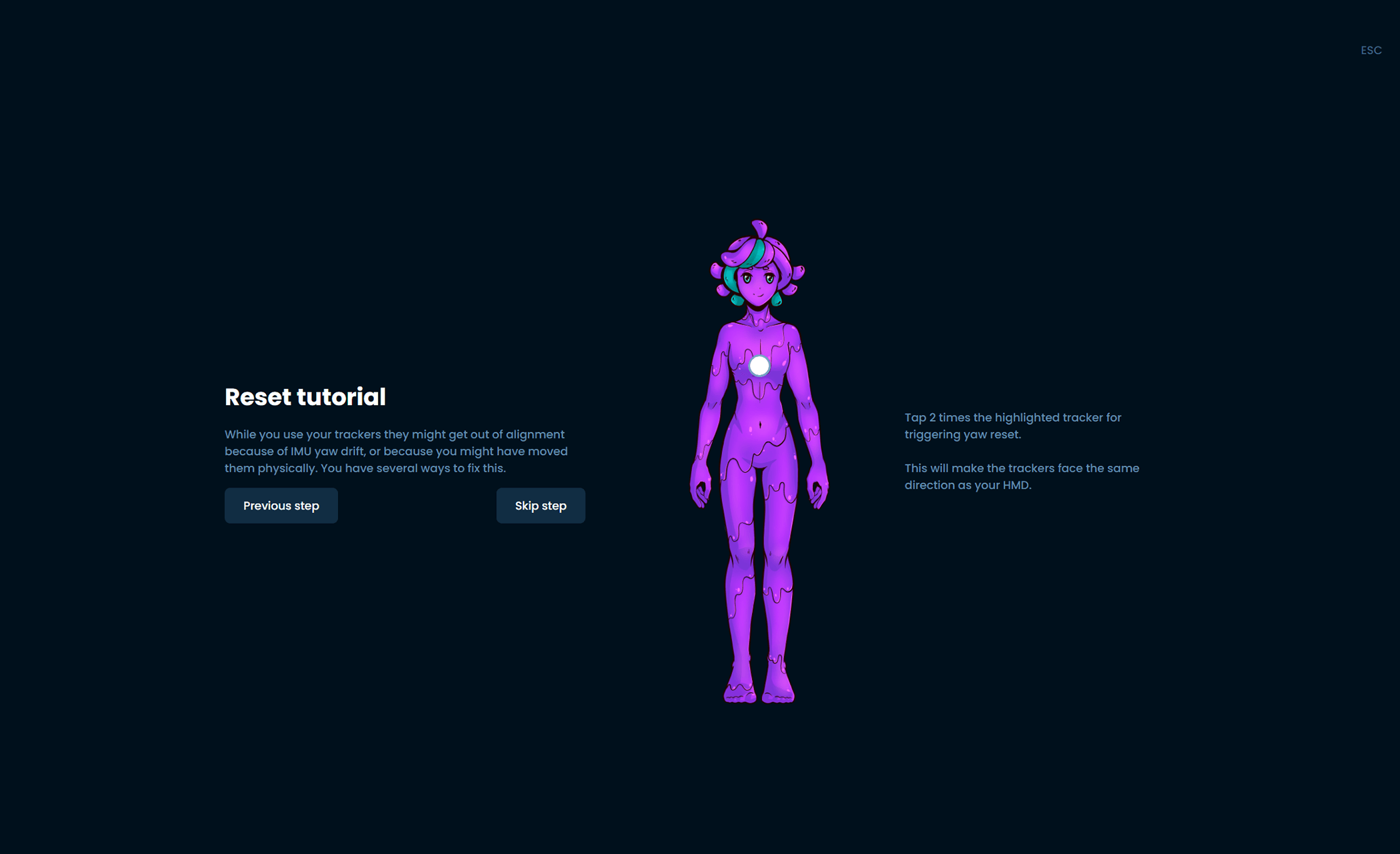
- Tapping Chest - Yaw reset, resets the trackers to assume they are facing their defined mounting orientation.
- Tapping Left Thigh - Full reset, resets the trackers to the assumption that you are in an I-pose.
- Tapping Right Thigh - Mounting reset, resets the trackers to an estimated mounting orientation. You must be in the ski position as illustrated in the mounting calibration wizard for this to work.
-
To move through this process, follow the steps shown and tap the indicated tracker.
Configuring Proportions
-
The last configuration is for SlimeVR to figure out what your proportions are! This is a vital step to replicating your movements in virtual space.
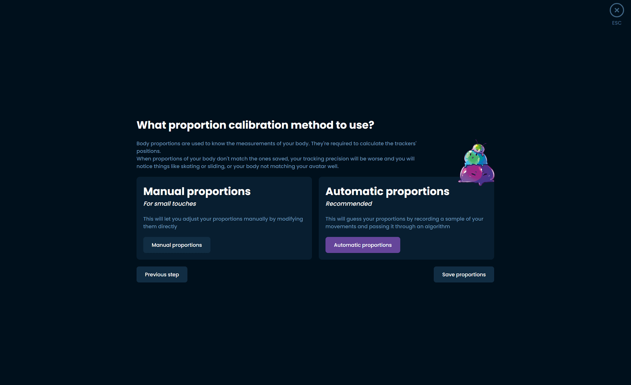
If you are using SlimeVR with SteamVR, you can automate this process. Make sure that you are wearing your trackers and your headset, and that SteamVR is running. It is very important to have a properly set floor from your headset as well before trying this.
If you are not using SlimeVR with SteamVR, you will have to manually set your proportions.
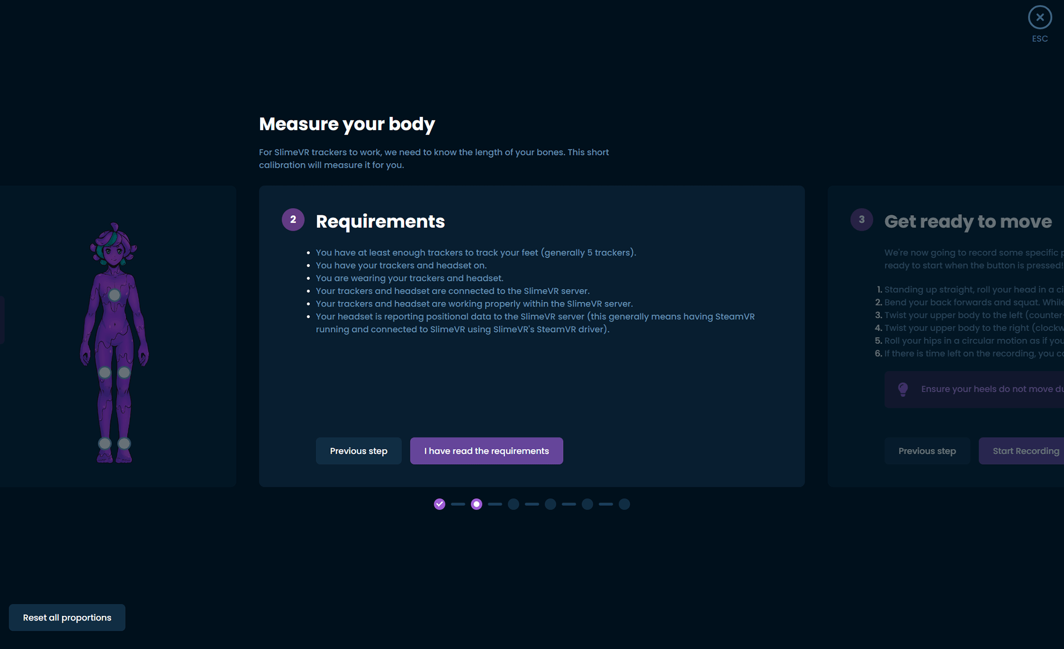
-
Follow the prompts in order to have SlimeVR measure your proportions automatically.
Note: Automatic proportions will not work if you do not have your headset on and SteamVR running. Do not lift or move your feet at all during this process.
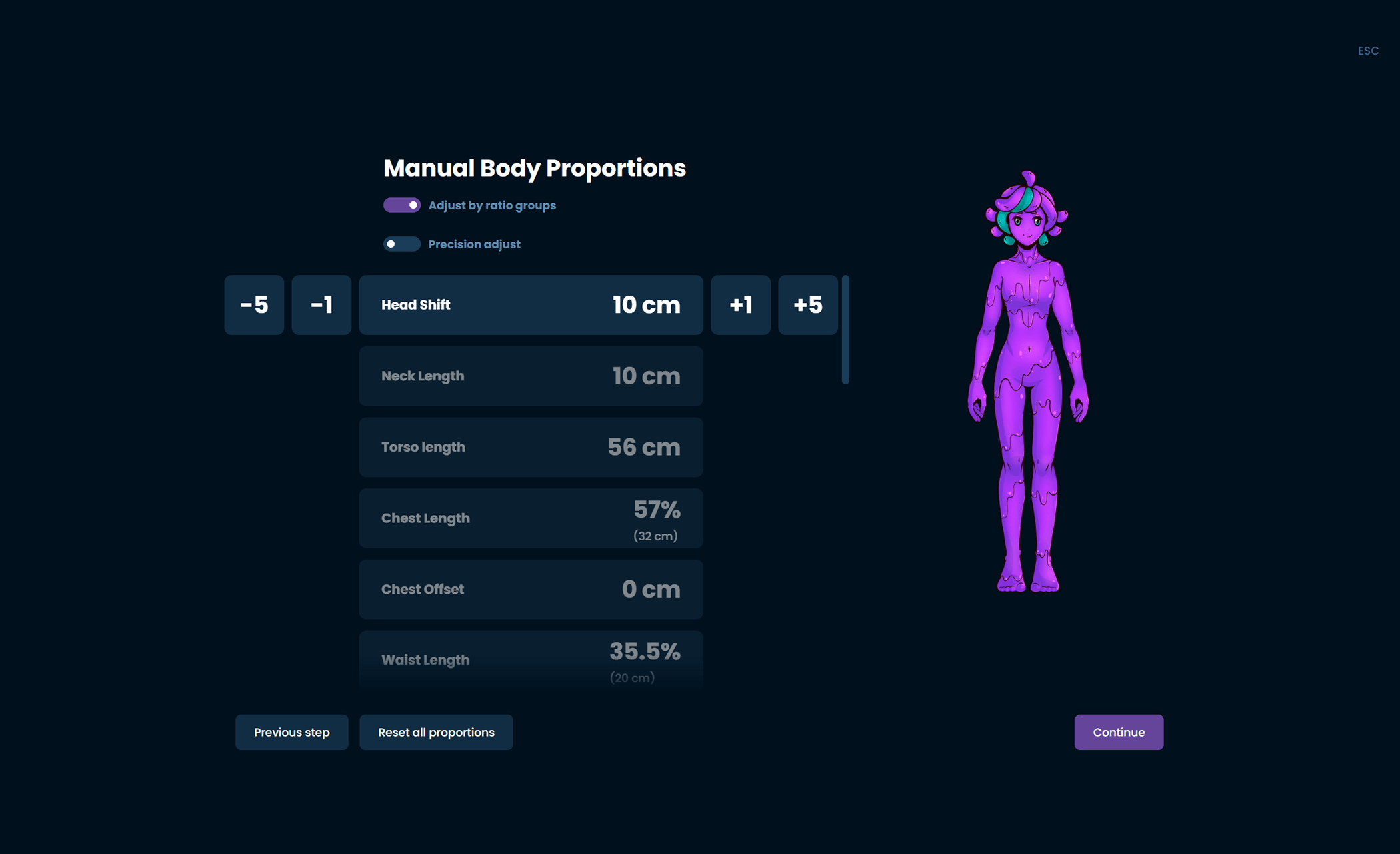
Manual Proportions
If you are not using SteamVR you will have to manually set each of these values or use VRChat OSC Query to enable the use of automatic proportions. For more information on how to measure each value please refer to the information at the top of the body proportions configuration page.
For more information on how to set up VRChat OSC Query please refer to the [mobile installation]
Final settings
The last step is to go to the settings page and set up the specifics of how you want to use it.
Spawning trackers
The SlimeVR Server now has automatic assignment of SteamVR trackers, this shows what will activate for each set with that toggle on:
- Lower-Body Set (5 trackers) - Chest, waist, knees and feet.
- Core Set (5 trackers with one extension) - Chest, waist, knees and feet.
- Enhanced Core Set (5 trackers with three extensions) - Chest, waist, knees and feet.
- Full-Body Set (7 trackers with three extensions) - Chest, waist, knees, feet and elbows.
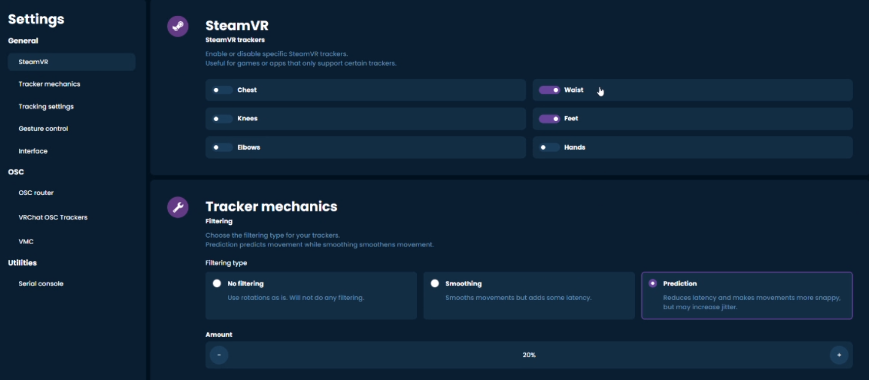
Enabling trackers on SteamVR
- Make sure you installed SlimeVR with the installer to have the right SteamVR driver.
- Make sure the SlimeVR addon is enabled in SteamVR Settings > Startup/Shutdown > Manage Add-ons.
- Make sure you have SteamVR Trackers enabled in the SlimeVR settings.
OSC
If you decide to use OSC Trackers with the Steam version of VRChat, make sure you first disable all of the SteamVR trackers before going to the OSC settings.
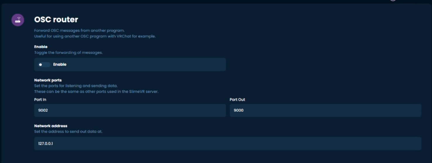
From here you will need to make sure that the network address is set correctly.
Software directly on Quest
If the server is running on the Quest, leave the address as 127.0.0.1.
Software on other device (Phone, laptop, older PC etc)
If the server is not on the Quest, put in your Quest's IP. You can get this by opening the Quick Settings menu on your Quest, selecting Wifi, your currently connected network, and scroll down and click the arrow. The IP address is listed there video tutorial on how to find your Quest's IP.
Then, you can toggle on which locations that you need using the following suggestions:
- Lower-Body Set (5 trackers) - Waist, knees and feet.
- Core Set (5 trackers with 1 extension) - Chest, waist, knees and feet.
- Enhanced Core Set (5 trackers with 3 extensions) - Chest, waist, knees and feet.
- Full-Body Set (7 trackers with 3 extensions) - Chest, waist, knees, feet and elbows.
If you wish to change to SteamVR trackers, you will have to disable OSC and turn the SteamVR trackers back on first.
For more information on OSC, please visit the OSC page.
Congratulations, your Slime trackers should now be set up!
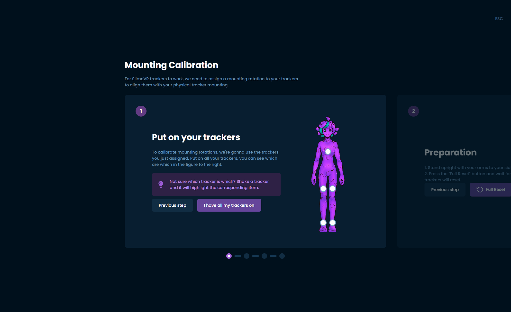
Putting them on again after this setup
The next time you want to use your trackers, all you need to do is put them on and go through the Mounting Calibration wizard quickly. All other settings should be saved from your initial setup! Make sure that you have your headset on and SteamVR running before going through this process.
Having problems?
My trackers in SteamVR aren't set up properly
If this is in SteamVR before launching any games, go to Settings > Controllers > Manage Vive Trackers, and manually set up the trackers' positions to match the virtual trackers' names. If this is in game it could be a calibration issue!
My trackers don't connect to my Wi-Fi
If you are having issues with your Wi-Fi, you can try an alternative Wi-Fi network or host a hotspot with your PC.
For all other problems, check the Common Issues page
Common Issues
This page aims to list and provide solutions to frequently encountered issues. If nothing here answers your question, or a given fix does not help, please feel free to ask your question in the #support-forum on the SlimeVR Discord. Make sure you mention all of the steps you have tried from here when asking for help. Keep in mind that some solutions may not apply to your SlimeVR Trackers, especially if they are DIY or purchased from a third-party seller.
- Network profile is currently set to Public
- SlimeVR Feeder App not connected
- Feeder App window closes immediately after opening
- The SlimeVR Server won't start
- The SlimeVR window is stuck as a tiny window
- SlimeVR GUI crashes immediately / "panicked at ... WebView2Error" / WebView2 is missing
- SlimeVR GUI keeps timing out / "Connection lost to the server. Trying to reconnect..." repeatedly
- The Wi-Fi Settings window outputs ERROR
- The Wi-Fi Settings window outputs symbols and nothing else
- Tracker can't connect to WiFi
- The trackers are connected to Wi-Fi but can't find the server
- The trackers are connected to the SlimeVR server but don't show up
- The trackers are connected to the SlimeVR server but aren't turning up on Steam
- My tracker keeps flashing
- My aux tracker isn't working
- Sensor was reset error
- Trackers are drifting more than expected
- Ankle and foot trackers appear as one tracker
- My trackers are bound to the wrong body part in SteamVR
- Moving one tracker moves other body parts in VRChat
- Trackers are moving in the wrong direction when I move
- My feet sink into the floor / I'm sliding a lot
- My feet are incorrect/move incorrectly
- My avatar floats above the ground
- My legs don't bend
- My legs cross when sitting down
- One of my leg is higher than the other
- AutoBone / Automatic body proportions calibration isn't working
- No serial device appears / "Looking for trackers" / "Connection to serial lost, Reconnecting..."
- Please specify upload_port while updating firmware / trying to upload firmware fails
- Quest Pro controllers cause high latency / lag
- Magnetometer value is
0.0/0.0/0.0on SlimeVR server - References
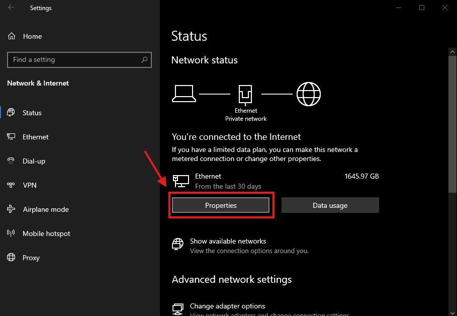
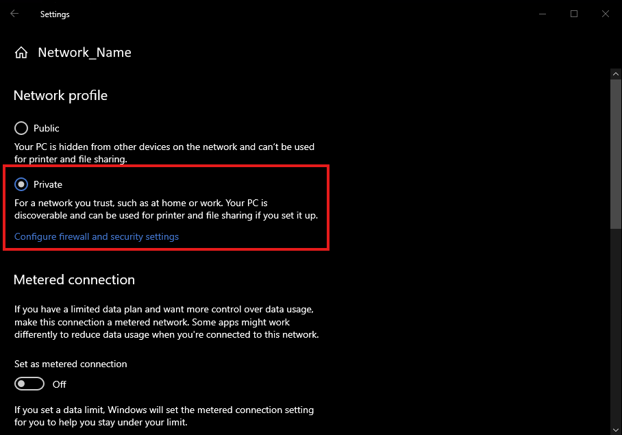
Network profile is currently set to Public
If your network settings in Windows are set to "Public Network", it can lead to issues with how your SlimeVR Trackers connect to your PC. To change this you can do the following:
Windows 10
Open your network settings via Windows Settings > Network & Internet > Properties. Switch the setting called "Network Profile Type" to "Private Network".
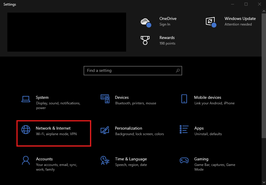
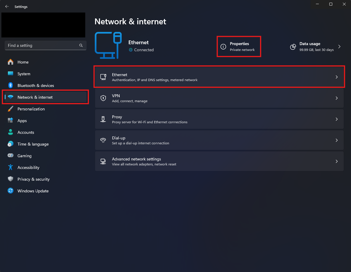
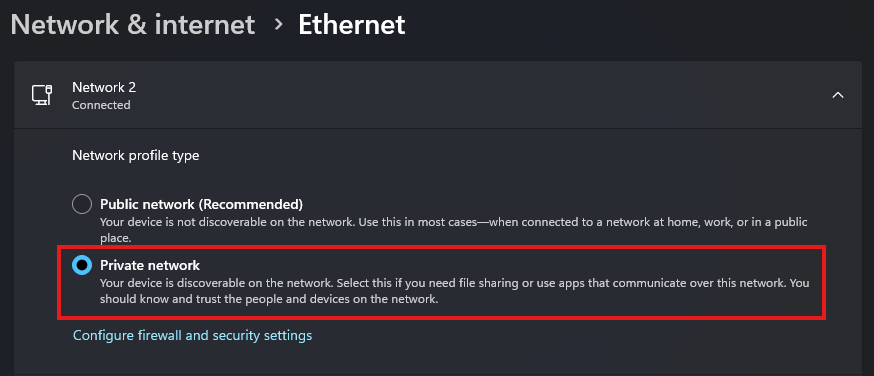
Windows 11
Open your network settings via Windows Settings > Network & Internet. You can either click "Properties" or "Ethernet/WiFi" depending on how your PC is connected. From there, switch the setting called "Network Profile Type" to "Private Network"
SlimeVR Feeder App not connected
Ensure both SlimeVR and SteamVR are running and that the SlimeVR Feeder app is enabled in the Startup Overlay Apps. Follow the guide below on enabling it.
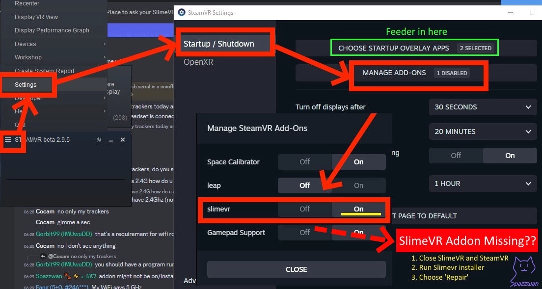
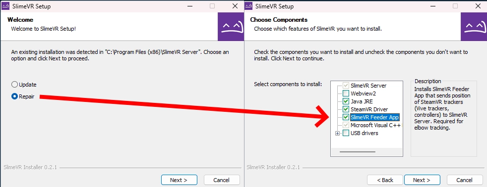
If the app does not appear in SteamVR, you may have to run the SlimeVR installer again in Repair Mode. Make sure "SlimeVR Feeder App" is ticked before continuing.
Feeder App window closes immediately after opening
This is intended behaviour on later versions—the Feeder app continues to run in the background after the window auto-closes.
The SlimeVR Server won't start
- If the error is related to ports, ensure all other SlimeVR Server instances are closed. If it continues, restart your PC.
- This may also be caused by Java not being installed or issues with your Java installation. Running the installer linked in the Installing the server page again should handle this.
The SlimeVR window is stuck as a tiny window
Update your SlimeVR Server using the installer
SlimeVR GUI crashes immediately / "panicked at ... WebView2Error" / WebView2 is missing
It's possible that you don't have the required WebView2 component installed, you can download the WebView2 installer from https://developer.microsoft.com/en-us/microsoft-edge/webview2/consumer/. To ensure that WebView2 installs properly, run the WebView2 installer as an administrator (right-click, then select Run as Administrator) and make sure the installer is running from the C: drive (ex. C:\MicrosoftEdgeWebview2Setup.exe) and running it from there.
SlimeVR GUI keeps timing out / "Connection lost to the server. Trying to reconnect..." repeatedly
- If your SlimeVR GUI is repeatedly timing out from the SlimeVR server (check the logs), you may be able to fix this by running the following command in an administrator console:
netsh int tcp set supplemental internet congestionprovider=default. This is caused by non-default Windows network configurations commonly used by modified OSes. - Alternatively, try running the SlimeVR installer in repair mode.
The Wi-Fi Settings window outputs ERROR
Try resetting your tracker, this may fix the issues immediately. Try connecting the tracker to a different USB port, and/or try a different USB cable. If the issue persists, your COM port may be being hogged, which can be tested by going through the firmware update process in VSCode (as it has more verbose error messages). If this is the case, close any application that might be hogging the ports (VSCode and Cura are often the cause).
The Wi-Fi Settings window outputs symbols and nothing else
There are two common causes that you should check:
- Make sure that you have the right driver installed.
- Check that your PIO firmware upload worked. If you have multiple firmware versions open in VSCode you will have to set the correct one to default to upload.
Tracker can't connect to WiFi
The two common issues that cause this error are:
- Make sure you are connecting to a 2.4GHz network, 5GHz networks are not supported.
- Check your SSID for special characters. At the time of writing SlimeVR only supports network SSIDs that contain alphanumerical characters.
- Make sure you are using WiFi channels 1-11. Avoid using channels 12-14 because connection issues may occur.
- Ensure WPA3 WiFi security is not being used, as the SlimeVR trackers do not support this security protocol. We recommend using WPA2, which is fully supported by SlimeVR.
- Try restarting your router to see if this resolves the issue.
- When using a WiFi 7 router, try disabling MLO or switching from 'Performance' to 'Compatibility' mode (sometimes called 'Max interoperability' mode).
If all of this is correct, you can check your gateway's list of connected devices to see if all your trackers are connecting. If a tracker is not connecting even after using the same firmware upload with hardcoded Wi-Fi details there are two additional steps you can check:
- Check if your Wi-Fi has reached its maximum allowed Wi-Fi connections. You can test this by disconnecting devices and then trying to connect your trackers again.
- If you hard coded your Wi-Fi settings in
platformio.initry connecting your trackers via USB and pushing new Wi-Fi details. You may find this either fixes your connection or provides you with additional details on why the connection is failing.
The trackers are connected to Wi-Fi but can't find the server
Check that you do not have two copies of the SlimeVR server running, as only one of them will show trackers connected.
If only one server is running, this is most likely a firewall issue, go to SlimeVR Server folder and run firewall.bat as administrator to add the firewall rules to Windows Defender Firewall.
If you are still having trouble, try manually adding the SlimeVR Server to your firewall.
- Go to Settings > Network & Internet then click on the text link Window Firewall (you may have to scroll down).
- In the firewall window, click the link Allow an app through firewall.
- Click the Allow another app... button, and then Browse... in the opened Add an app window. If your options are greyed out in the Allowed apps window, click the Change Settings button to allow changes.
- In the File name text box, type
*.*and press enter before navigating toslimevr.jarin your SlimeVR server folder and select it (if you cannot see files in this folder, try typing*.*and pressing enter again to show all files). - Click the Add button to add the file to your firewall settings.
- Finally, make sure both public and private checkboxes are selected in the Allowed apps window before clicking OK to save the changes.
If adding SlimeVR to your firewall has not worked, you can try to diagnose the issue further with the following steps:
- Make sure the computer's Ethernet/Wi-Fi connection is set to Private.
- Make sure Network Discovery is enabled on your active network interface.
- Disable any VPN software or VPN-enabled hardware.
- Make sure your trackers are not connected to a Guest WiFi network.
- Make sure the WiFi network does NOT have AP Isolation enabled.
- Delete the SlimeVR configuration: Close SlimeVR and delete the config folder at
%AppData%\dev.slimevr.SlimeVR. - If you install and run the SlimeVR server on another device, then close it, the trackers should reconnect to the previously used server.
- Temporarily disable Windows Defender Firewall or any other antivirus to test if the trackers connect.
- If the trackers only show up on SlimeVR when Windows Defender Firewall is disabled, then you have a problem with your firewall.
- Try pinging the tracker from your computer to see if it can be reached by opening Command Prompt (CMD) and run the command
ping <IP>, where<IP>is your tracker's IP (ex.ping 192.168.0.1). You can find the tracker's IP using the "Serial console" under the "Settings" tab of the SlimeVR GUI.- If the command outputs something like
Reply from 192.168.XXX.XXX: Destination host unreachable., then you likely have a problem with either your router or your firewall. - If the command outputs something like
Reply from 192.168.XXX.XXX: bytes=32 time<1ms TTL=63, then you likely have a problem with either your network adapter or your network settings. You may need to enable broadcast packets (or something similar) on your router, as SlimeVR trackers broadcast to255.255.255.255to discover your SlimeVR Server.
- If the command outputs something like
- Try hosting a Wi-Fi hotspot either from your computer or your phone and connect your trackers to it to see if they will show up on SlimeVR using it.
- If the trackers don't show up on SlimeVR, then you likely have a problem with either your trackers or your computer. It may be worth trying disabling your Windows Defender Firewall as per the first step, but using this Wi-Fi hotspot instead.
- If the trackers show up on SlimeVR, then you likely have a problem with either your router or the network adapter you connect to your router with.
- Re-flash the firmware to an older version.
If none of these steps have helped you, you can find information about getting further help at the top of this page.
The trackers are connected to the SlimeVR server but don't show up
This is usually the result of an issue with the IMU. Plug in your Wemos D1 Mini and check through the serial console under settings in the SlimeVR server. You may see an error like one of the following:
[ERR] I2C: Can't find I2C device on provided addresses, scanning for all I2C devices and returning
[ERR] I2C: No I2C devices found
[ERR] I2C: Can't find I2C device on provided addresses, scanning for all I2C devices and returning
[DBG] I2C (@ D2(4) : D1(5)): I2C device found at address 0x68  !
[ERROR] [ErroneousSensor:0] IMU of type MPU6500 failed to initialize
The most common reasons for errors with the IMU are the following:
- You accidentally set the IMU wrong (i.e. set as MPU6050 when you have an BNO085)
- You accidentally selected the wrong board type (i.e. set as BOARD_SLIMEVR instead of BOARD_WEMOSD1MINI)
- The wiring is wrong (e.g. accidentally swapping around D1/D2 and SDA/SCL)
- There's an issue with the soldering (e.g. not enough solder, cold joint, or bridging between SDA and SCL)
- You're using a breadboard (Without soldering connections, the IMU often won't be able to communicate with the microcontroller)
- There's an issue with the IMU itself (e.g. burned trace while soldering, or the chip is downright DOA)
The trackers are connected to the SlimeVR server but aren't turning up on Steam
- Make sure you installed SlimeVR with the installer to have the right SteamVR driver.
- Make sure the SlimeVR addon is enabled in SteamVR Settings > Startup/Shutdown > Manage Add-ons.
- Make sure you have SteamVR Trackers enabled in the SlimeVR settings.
My tracker keeps flashing
This is intended behavior, the number of flashes lets you know the current status of your tracker. Check the top of the the setup page for more info.
My aux tracker isn't working
- Ensure that the tracker was powered off before the aux tracker was connected.
- In order to make sure your aux tracker is set up, you need to specify it in your
defines.huploaded to the primary tracker's firmware. Check the bottom of the section mentioning defining the pins on the configuring the SlimeVR firmware page. Alternatively, you should ensure that you have correctly soldered VCC to AD0 on your aux tracker IMU.
Sensor was reset error
Check your INT wire, there is either a bad connection or you have it connected to the flash pin. If you are building your tracker on a breadboard, your connections may be not firm enough and cause this error.
Trackers are drifting more than expected
- Make sure that the tracker is placed on a solid, vibration free surface when powered on. The sensors need to calibrate for 10-20 seconds in a stable environment. If your trackers use an IMU besides BNO085 and ICM-45686, you may need to perform additional IMU calibration.
- Additionally, after 15 or more minutes of use, take the trackers off and place them flat for 10-20s before putting them back on. This ensures that the IMU adjusts to your body temperature.
Ankle and foot trackers appear as one tracker
This is normal. SlimeVR combines the position of the ankle tracker with the rotation of the foot tracker—which means SteamVR only reports one foot tracker.
My trackers are bound to the wrong body part in SteamVR
If this happens in SteamVR, make sure your trackers are assigned to the right body parts in SlimeVR. Do not touch the assignments in SteamVR.
Moving one tracker moves other body parts in VRChat
- Ensure that IK calibration range is set to 0.2 in VRChat.
- Ensure that Legacy Calibration and Legacy IK are both disabled in VRChat
Trackers are moving in the wrong direction when I move
- Use the Automatic mounting calibration instead of manual.
- Make sure your mounting orientations for your trackers in the server are correct to where they are on your body (you may have to lie about them for certain setups)
DIY-Only: You may have specified a wrong
IMU_ROTATIONvalue in yourdefines.hfile. Take note of which trackers are the issue and refer to the configuring the SlimeVR firmware page to get the board's rotation right. If it’s only off by a few degrees, shift your trackers inwards or outwards a bit, then redo automatic mounting calibration.
My feet sink into the floor / I'm sliding a lot
This will be due to either your physical or bone length setup. Try:
- Making sure "Skating correction" and "Floor clip" are enabled in the SlimeVR Settings > Tracking settings (doesn't work for Quest Standalone for now).
- Running through the Automatic Calibration again.
- Adjusting your IRL tracker mounting.
My feet are incorrect/move incorrectly
- Ensure foot mounting reset is completed after mounting calibration in the SlimeVR server.
- Try changing the angle of your feet; higher or lower angles may work better depending on your body type. They should not be tilted to either side during foot calibration.
My avatar floats above the ground
- Make sure your floor level is correct by redrawing your boundary. If on Quest or other standalone headsets, clear boundary history.
- Ensure your real height is your actual IRL height in both SlimeVR and VRChat
- This may also be caused by a niche issue with specific avatars, try switching to an alternative avatar and recalibrating in VRChat.
- If you're using a Quest headset, turn off
Use in a lying position(or similar options) in the headset settings. This can cause both floating and sinking issues.
My legs don't bend
- Make sure you have upper leg trackers above your knees and assigned as "Thigh" trackers as well as ankle trackers just above your ankles assigned as "ankle" trackers.
- Make sure your ankle trackers are on your ankles and not your feet.
My legs cross when sitting down
- Make sure your feet are positioned no closer than 10cm apart from each other in mounting calibration
- Try mounting your upper leg trackers further outwards at an angle
- Try mounting your upper leg trackers higher on your thighs or lower on your upper legs depending on your build.
- Reset your body proportions and height in the body proportions menu.
- Use yaw reset to correct leg crossing: assigning a keybind for resetting.
One of my leg is higher than the other
Shift your upper leg trackers a bit; try out other mounting positions and orientations for your upper leg trackers
AutoBone / Automatic body proportions calibration isn't working
If AutoBone isn't working properly for you, you can find a list of common issues and debugging information in the "Common Issues / Debugging" section of the body proportions configuration page.
No serial device appears / "Looking for trackers" / "Connection to serial lost, Reconnecting..."
If you are having trouble with your tracker(s) not being detected for the "Connect trackers" step, not showing up in the serial console, not showing up in the web firmware tool, or not being detected in VSCode, then make sure you check the following:
- If you are using official trackers, ensure that they are turned on and the blue light is blinking. If the blue light is not blinking, there may be other issues.
- For most DIY trackers, they should be turned off as a safety precaution as the ESP should be powered by USB directly.
- If you are using DIY trackers, ensure you are plugging in the microcontroller module (the ESP, like Wemos D1 Mini which usually has Micro USB), not the charging module (TP4056, which usually has USB C).
- Ensure that your cable is a data cable. Some cables are charging only and therefore cannot be used to connect to serial.
- Ensure that the appropriate drivers are installed. For official trackers and most DIY trackers, you'll need CH340/CH341 drivers. Some other DIY trackers need FT232 drivers.
- CH340/CH341 drivers are installed when installing SlimeVR, but can also be found at https://www.wch-ic.com/downloads/CH341SER_EXE.html.
- Note: Some ESP breakout boards (DIY) come with counterfeit CH340 chips, which don't work with the latest drivers. To work around this, you can use https://github.com/SHWotever/FakeCH340DriverFixer#how-to-use (not provided by SlimeVR, please be careful) to automatically detect these fake chips and correct the driver version. You can also find information on how to spot the counterfeits on the same page.
- FT232 drivers can be found at https://ftdichip.com/drivers/vcp-drivers/.
- CH340/CH341 drivers are installed when installing SlimeVR, but can also be found at https://www.wch-ic.com/downloads/CH341SER_EXE.html.
- Make sure the cable is seated properly, this is usually accompanied with a click as it seats into place.
You can easily determine the type of chip you have using Device Manager. Open Device Manager, and under one of the categories (usually "Ports (COM & LPT)" or "Other devices") you'll find one of the following:
- CH340: "USB-SERIAL CH340"
- FT232: "USB Serial Converter"
Please specify upload_port while updating firmware / trying to upload firmware fails
This error indicates there is interference between your computer and the tracker. Check the following:
- Make sure your USB cable from the tracker is plugged firmly into your PC.
- Make sure that your USB cable is a data and charging cable (it is suggested you try other cables or devices with the cable).
- Make sure that your drivers are up to date.
- You may have a counterfeit CH340 module on your DIY tracker. Try running FakeCH340DriverFixer for compatible drivers.
Additionally, this can be caused by software hogging COM ports (VSCode and Cura can be the cause of this).
Quest Pro controllers cause high latency / lag
Quest Pro controllers can use 2.4 GHz Wi-Fi to connect to your headset, this can cause interference with SlimeVR trackers as they also use 2.4 GHz Wi-Fi. The easiest current solution is to change your 2.4ghz WiFi channel through your router, though this may not always work. If you wish to find the Quest Pro controller's Wi-Fi, it should be called something like "DIRECT-Meta-XXXX". You can read the Meta support article for Wi-Fi troubleshooting for the Quest Pro controllers for more information.
Magnetometer value is 0.0/0.0/0.0 on SlimeVR server
This is intended behavior due to hardware limitations of the ESP8266. There is not enough time to fetch the raw data and send it to server, because ESP8266 utilizes bit-banging and time for I2C transactions is limited. It does not mean your sensor is dead or SlimeVR is not using magnetometer sensor.
For more information, checkout this github issue.
References
Created and updated by calliepepper, edited by emojikage, spazzwan, butterscotch.v, Smeltie, and Aed. Majorly reformatted and updated by Amebun.
Safety Guides
Download the official instructions and safety guide here.
Warning!
Official SlimeVR Trackers are fitted with a protective plug at the extension port. Please leave the plug in place whilst the port is not in use.
EN: Instructions for safe use
To prevent damage or malfunction and ensure correct use of the product, please observe the following:
- Do not expose the product to water or moisture.
- Do not expose the product to heat.
- The AUX port is only intended to be connected to official auxiliary trackers. Improper use may cause the product to malfunction.
- Do not plug or unplug extensions while the product is powered on.
- Do not overtighten straps. This can reduce circulation and lead to injury.
This product generates RF radiation. This could cause interference with cardiac pacemakers, implanted defibrillators (ICDs), and other implants. Maintain at least 15cm / 6" separation between the implanted device and the product, and follow the implant safety instructions.
The product contains a lithium battery. Improper handling of a lithium battery can cause damage or malfunction, which in extreme cases can pose a risk of: heat generation, fire development, smoke or gas development, and explosion.
- Do not leave the product unattended during charging.
- Only charge the product using an external power supply rated for 5V DC.
- Only charge the product in ambient temperatures ranging from 10°C to 40°C / 50°F to 104°F.
- Switch off the product after use and when charging.
- Store away from direct sunlight.
- When not using the product for a prolonged period of time, charge them intermittently to ensure battery health.
- Only dispose of this product at special collection points.
Created by vyolex. Translations provided by the community.
Updating Your Tracker's Firmware
On this page you will find several ways to flash SlimeVR trackers and how to manually recover official SlimeVR trackers.
Index
- Update Your SlimeVR Trackers - How to update your official SlimeVR trackers.
- USB Recovery - Recover trackers after failed update.
- Manual Wireless Updates - Rolling back firmware.
Update Your SlimeVR Trackers
Under normal circumstances, official SlimeVR trackers should be updated using the icon that appears on the trackers in the main menu
![]()
![]()
Upon clicking the update icon, you should be met with the following screen, please select the trackers you wish to update and click "Update Selected Trackers".
![]()
Now, turn the trackers selected for the update off and on again!
Do not unplug or turn off the tracker during the upload process unless told to do so, it may make the tracker unusable.
![]()
Now, the software will upload the firmware to the selected trackers.
![]()
Next, the software will apply the updated firmware to the selected trackers.
![]()
And that's it! Your tracker(s) should now be up to date!
![]()
Now, turn the trackers selected for the update off and on again!
If a tracker has stopped working after the update, do not flash any other trackers and refer to the USB recovery section below to recover the trackers firmware.
Disclaimer
These steps linked below are tailored towards official SlimeVR trackers, the settings pictured not compatible with most DIY trackers! This method has the potential to mess up your tracker(s), so please read the following warnings carefully:
-
Do not turn off your trackers during the flashing or applying update processes.
-
After flashing, ensure that your tracker is functional before turning it off.
-
If a tracker has stopped working after flashing it wirelessly, Please try fixing it first by performing a USB recovery before continuing with the other trackers.
-
Uploading unofficial/unsupported firmware might affect your tracker's functionality and may void your warranty.
USB Recovery
This method should only be used when wireless (OTA) is not an option. You are expected to disasemble the tracker during these steps, this does not void your warranty.
This method requires the following items:
- A data capable USB-C cable (the included one should suffice).
- A full-size PH1 (Phillips) screwdriver (precision sets can strip out the screws).
- Conductive tool such as tweezers or a paperclip to bridge specified points (only needed for R11 & R12, R14 has a physical button).
If a screw strips out, you can use a rubber band, which is a common way to extract stripped screws
Disassembling The Tracker
Start by turning off your tracker and removing the strap. Use a pozidrive screwdriver (JIS and Phillips head may work but can strip out the screws) to undo the screws on the back of the tracker.
![]()
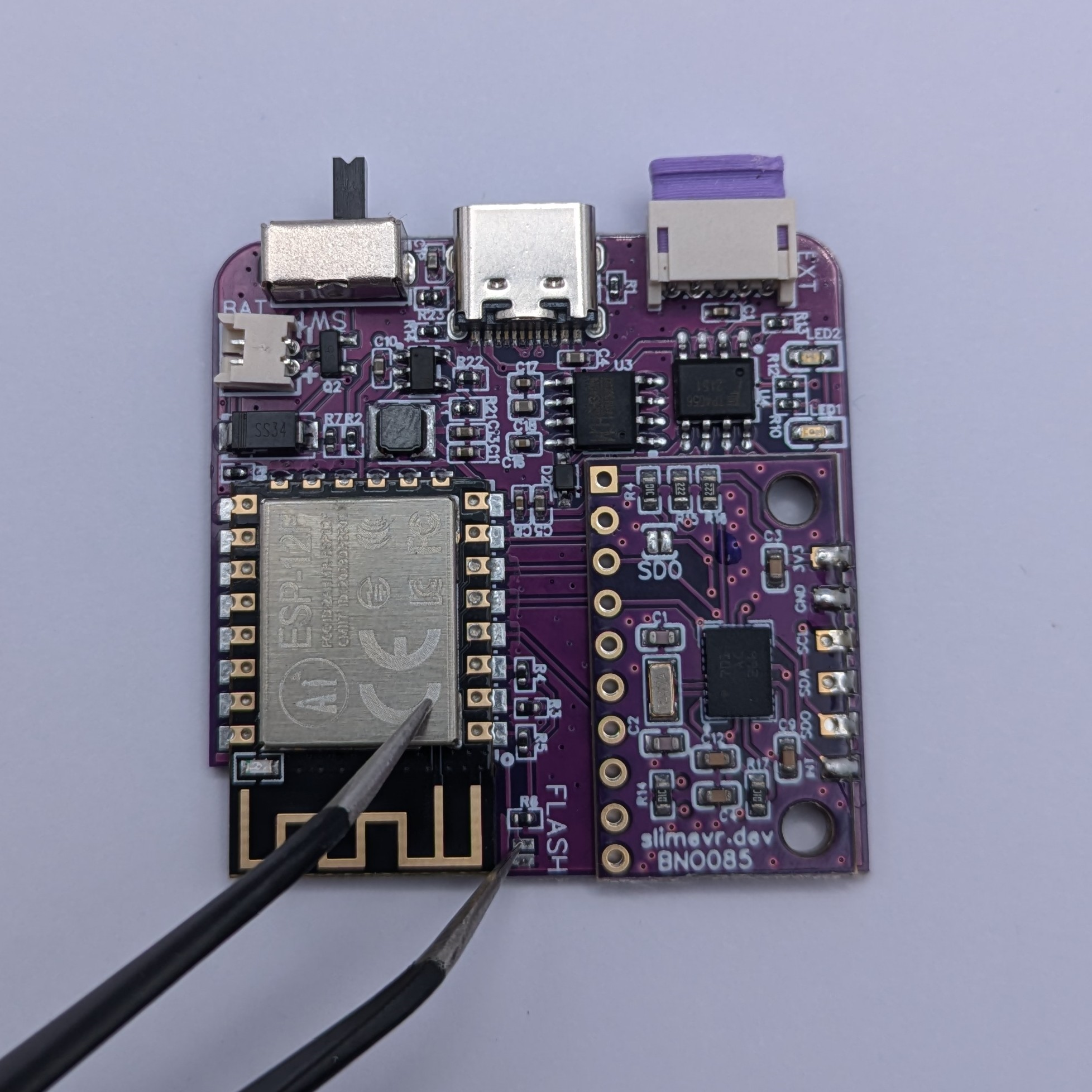
After removing the back cover you can carefully lift out the battery and lay it on the side. Then you can gently lift the PCB out at an angle by lifting the back side of the pcb (opposite side to the power switch and USB port).
Make sure not to touch the black antenna found on the rear left side. As this can be fragile!
![]()
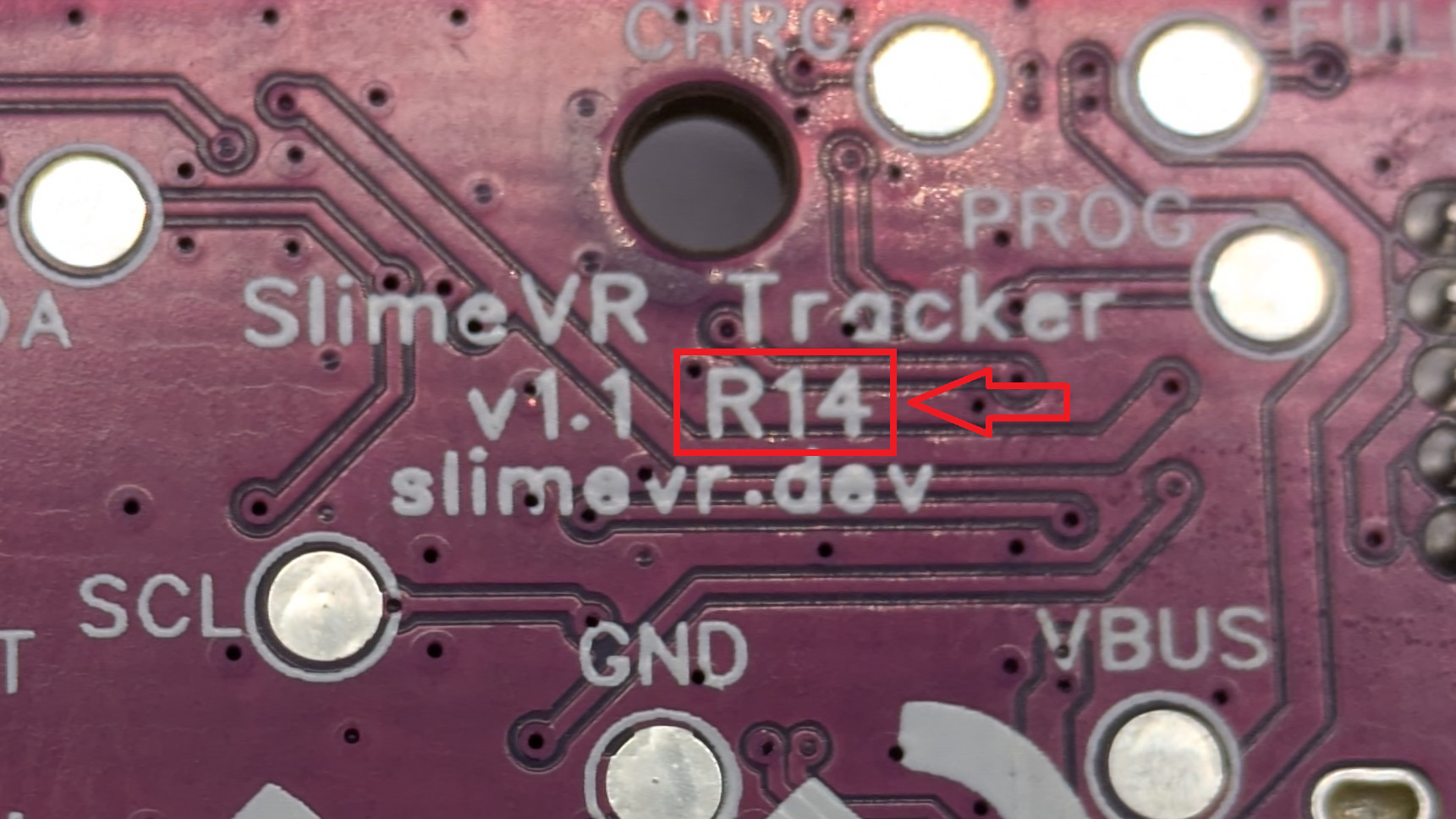
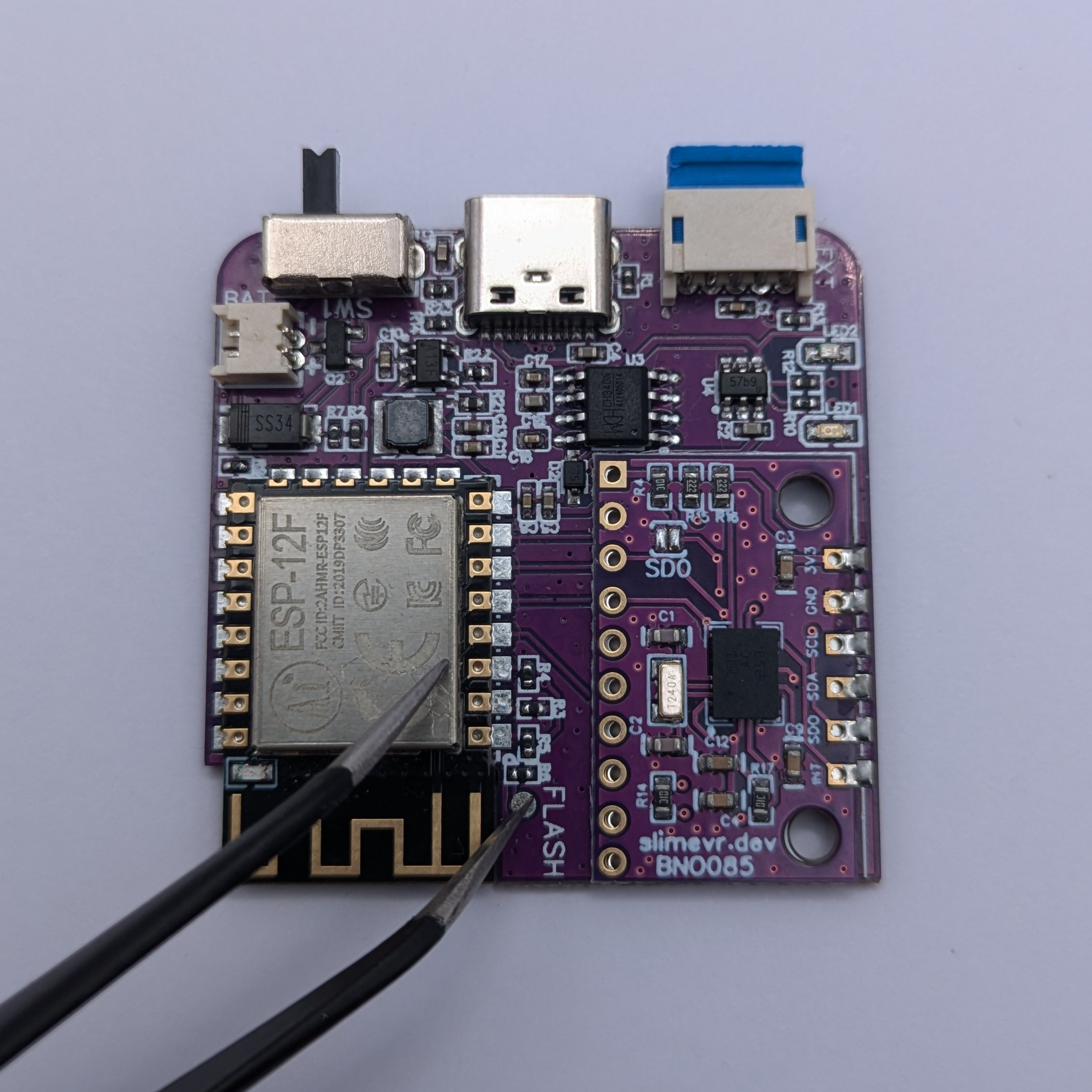
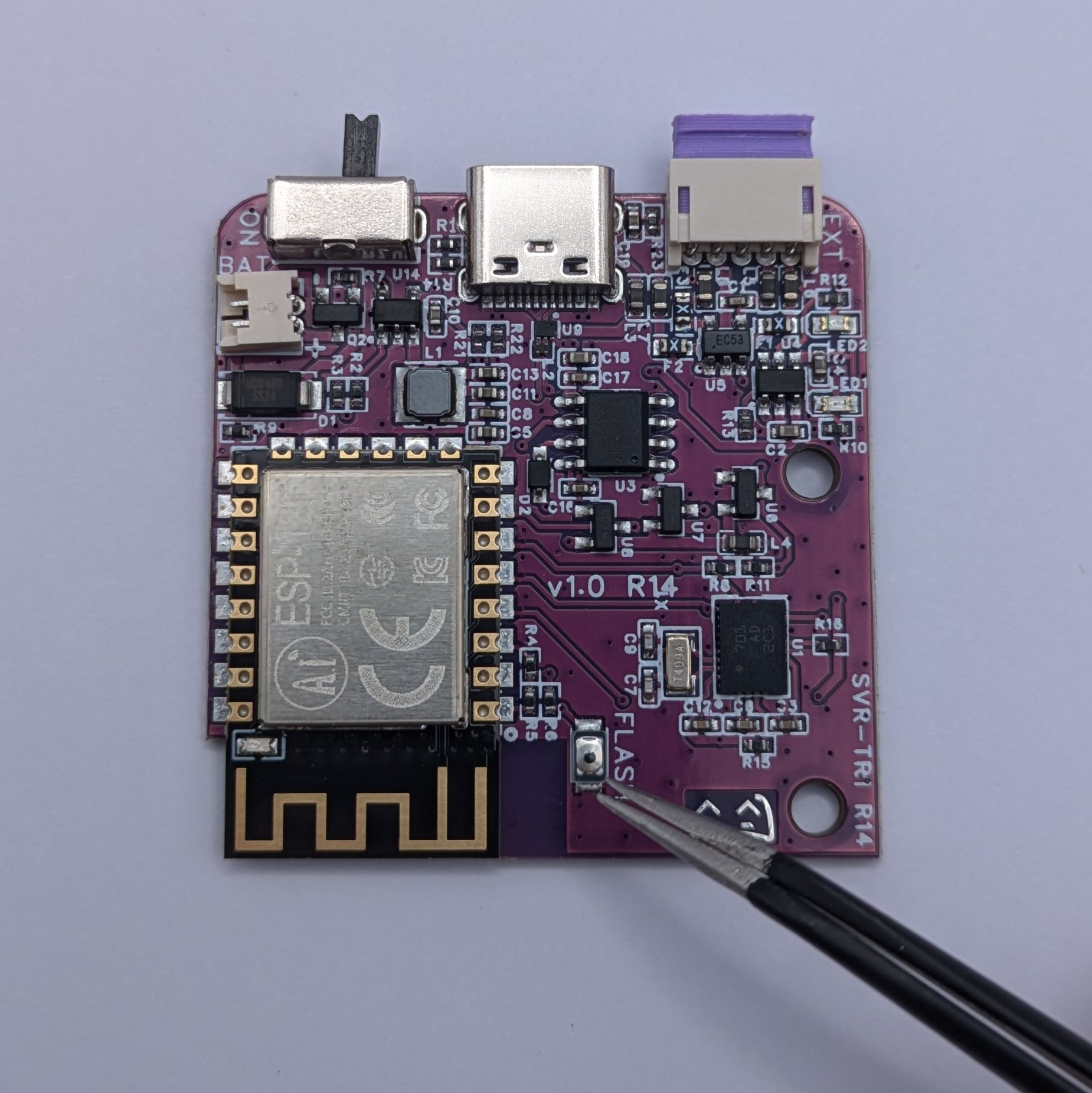
Inspect the back of the PCB to determine which revision you have.
Flashing Via USB (Serial)
You can find the "DIY Firmware Tool" under your settings menu in the SlimeVR software.
If you are using official SlimeVR, select "SlimeVR" for v1.0 or v1.1 BNO based trackers, or "SlimeVR v1.2" for v1.2 ICM based trackers, then select the Firmware source "SlimeVR-Tracker-ESP".
![]()
Select the latest available firmware by selecting the highest number in the list and clicking "Next Step".
![]()
For this step, your tracker needs to be plugged in (Do not turn it on yet). To Flash the tracker via USB select "serial", enter your Wi-Fi Credentials, and select the detected serial device from the dropdown menu (should be "USB-SERIAL CH340")
![]()
Now, for the next step, you will have to boot the tracker into bootloader mode by doing the following. You know you will have done it correctly if the blue LED gives a single fast blink when turned on using this method (the tracker needs to stay plugged in at this stage).
The version of the PCB, indicated as R1x, can be found on the back of the PCB and is important for the next steps!
| Revision | Steps |
|---|---|
| R11 | Turn on the tracker whilst shorting the second rectangular FLASH pad from the edge on the top side of the board to the metal shield of the microcontroller. |
| R12 | Turn on the tracker whilst shorting the circular FLASH pad on the top side of the board, and the metal shield of the microcontroller. |
| R14 | Turn on the tracker while holding the FLASH button on the top side of the board, you can let go after turning it on. |
Now click "Next Step", it should move on to the following screen where it will synchronize with the MCU. If this fails you might have to click retry. If that does not fix it, please retry the above step to ensure it's in bootloader mode (The Blue LED should give a single fast blue blink when powered on into bootloader mode).
![]()
The update should now be getting applied to the tracker.
![]()
The update should now be complete! If you get an error, try clicking retry. If that doesn't fix the problem, you may have to start over.
![]()
Finally, turn the tracker off and on again to reconnect it to the software. You can repeat the process for any other trackers that may need to be recovered.
Manual Wireless Updates
This method does not require disassembling the tracker or any cables, but it does require your tracker to already be connected to your Wi-Fi network. You can find the "DIY Firmware Tool" under the settings menu in the SlimeVR software.
If you are using official SlimeVR trackers, select "SlimeVR" and click "Next Step"
![]()
Select the latest available or desired firmware by selecting the version number from the list and click "Next Step"
![]()
To Flash the tracker wirelessly select "OTA" and then select all the trackers you wish to flash. For this step your trackers need to be on and connected to your Wi-Fi. When you have selected all the desired trackers, click "Next Step".
![]()
On this step you will have to turn the tracker(s) off and back on again, this way we can verify OTA is enabled and start flashing the tracker(s).
If the tool says:"Timeout", you need to click "Retry" and follow the instructions"on screen.
![]()
The tracker(s) will now start updating.
![]()
The tracker is now updated and ready to go!
![]()
If a tracker has stopped working after flashing it, do not flash any other trackers and refer to the USB flashing section above to recover it.
SlimeVR Terminology / Glossary
Definitions provided in this page are relative to their use in this documentation and for SlimeVR. They may be inaccurate or lack information relative to other, non-SlimeVR projects.
Table Of Contents
- SlimeVR Server
- SlimeVR GUI
- SteamVR Driver
- Feeder App
- Drift
- Session Calibration
- Full Reset
- Mounting Calibration
- Yaw Reset
- Reset Time
- Mounting Orientation
- VR Headset
- Smol Slime
- Breakout Board
- IMU
SlimeVR Server
The main SlimeVR application for receiving, processing, and outputting tracking data. This application runs locally using Java and connects to the SlimeVR GUI for a visual interface.
Synonyms
- SlimeVR (contextual)
- SlimeVR App
- SlimeVR Software
- SlimeVR Program
Related Terms
SlimeVR GUI
The visual interface for the SlimeVR Server. This GUI runs as a webview and connects to the SlimeVR Server over a websocket connection.
Related Terms
SteamVR Driver
The SlimeVR driver for SteamVR that sends the VR Headset position and rotation to the SlimeVR Server, receives tracking data from the SlimeVR Server, and uses the received tracking data to emulate Vive trackers in SteamVR.
Synonyms
- SlimeVR Driver
Related Terms
Feeder App
The feeder app is a program that connects to SteamVR and forwards tracker data from external sources to the SlimeVR Server. The trackers forwarded are generally VR controllers, Vive trackers, or Tundra trackers.
It is a common misconception that the feeder app also forwards the VR Headset tracking data, but that is done by the SteamVR Driver.
Synonyms
- SlimeVR Feeder
- Feeder
Related Terms
Drift
Commonly used to describe the loss of tracking accuracy that an IMU-based tracker experiences due to the accumulation of error over time. A tracker with high drift experiences a noticeable loss of accuracy within 20 minutes. Drift is also commonly measured as degrees per hour—with 1-3 degrees per hour being an acceptable level of drift for modern SlimeVR trackers at the time of writing.
Note that drift refers to the gradual loss of tracking accuracy and is inherent to the tracker itself. Poor Mounting Orientation Session Calibration by the user will lead to a constant level of tracking inaccuracy.
Synonyms
- Tracking accuracy
- IMU accuracy
Related Terms
- Accelerometer
- Gyroscope
- Magnetometer
- IMU
- Stay Aligned
- Reset Time
Session Calibration
There are multiple different session calibrations within the SlimeVR Server; these are commonly referred to as "resets". These are forms of calibration that are generally not saved and need to be done during each session of SlimeVR. See the Sub-Terms for the types of session calibrations.
Synonyms
- Full Reset
- Mounting Calibration
- Feet Mounting Calibration
- Software Calibration
- VRChat Calibration
Sub-Terms
Full Reset
A "full reset" is a Session Calibration that re-orients trackers to have zero rotation in the pitch and roll axes and have the same yaw axis rotation as the head tracker (usually a VR Headset), essentially "resetting" (or "zeroing") the "full" orientation. This is usually the first calibration used when starting a session with SlimeVR.
Mounting Calibration
Mounting Reset (or Mounting Calibration) is part of the Session Calibration that allows the server to automatically measure the mounting orientation of trackers. This is usually the second calibration used when starting a session with SlimeVR if the user chooses to use automatic mounting. When mounting calibration is used, the results of the calibration will override any manually set Mounting Orientation.
Mounting Calibration is also commonly referred to in conjunction with Feet Mounting Calibration, which allows the server to correct the orientation of feet trackers.
Synonyms
- Reset Mounting
- Automatic Mounting
- Automatic Mounting Orientation
Related Terms
Yaw Reset
A "yaw reset" is a Session Calibration that re-orients trackers to have the same yaw axis rotation as the head tracker (usually a VR Headset). Since this only calibrates the yaw axis, the user can be in any position where the trackers are all facing in their forward orientation with the head tracker. This is a calibration mainly used to correct for drift after a subjective amount of time since the last yaw reset or Full Reset.
Synonyms
- Fast Reset
- Quick Reset
Reset Time
Reset time refers to the rough amount of time a given IMU will take to accumulate enough drift to require a yaw reset. This is a subjective measurement and is based on how much drift a user will tolerate.
Related Terms
Mounting Orientation
Mounting orientation is a type of correction for SlimeVR trackers. It defines the server's measurement of the rotation of trackers with respect to how they are physically mounted to your body. This can be automatically set by the server (preferred) or manually corrected by the user (not recommended due to inaccuracy).
Synonyms
- Mounting Direction
- Manual Mounting
Related Terms
VR Headset
A VR headset is a head mounted device that tracks its position and rotation, usually with a display for each eye. For more information, see https://wikipedia.org/wiki/Virtual_reality_headset.
Synonyms
- Virtual Reality Headset
- HMD
- Head Mounted Device
- Headset
Smol Slime
A type of SlimeVR tracker that uses an nRF wireless dongle instead of WiFi to connect to the server.
Synonyms
- Smols
- Smol Trackers
Related Terms
- Big/normal slime (wifi-based slime)
Breakout Board
A type of PCB designed to simplify integrating one or more integrated circuits into a larger device. Breakout boards are typically used for IMUs, charging circuits, and microcontrollers, among other components.
Synonyms
- Breakout
- External PCB
Related Terms
- Microcontroller
IMU
An acronym for Inertial Measurement Unit. It is a type of integrated circuit that contains one or more devices used to measure movement. SlimeVR requires that an IMU integrates both an accelerometer and a gyroscope to allow for the measurement of acceleration and rotation relative to the last reset. As the IMU itself has no positional reference, it is susceptible to the unavoidable accumulation of error in its sensors over time, called drift. A low-quality IMU accumulates error faster than a high quality IMU.
Related Terms
- Drift
- Accelerometer
- Gyroscope
- Magnetometer
- Full Reset
- Mounting Calibration
- Yaw Reset
Updated and edited by Amebun.
DIY Trackers Guide
This guide helps you build SlimeVR trackers from scratch.
If you purchased a SlimeVR DIY Kit, see the DIY Kit page.
If this is your first time making DIY SlimeVR trackers, the DIY community recommends building:
- meowCarrier trackers (Wi-Fi-based)
- smol trackers (nRF-based)
PCB-based builds are strongly recommended over wired builds. Wired builds are more error-prone, easier to short, and tend to be less mechanically reliable due to wire fatigue or disconnections.
The Process
Before you start, decide on how many trackers you may need.
Next, you should decide if you want extensions.
The DIY community DISCOURAGES extensions:
- Extension cables tend to break even during normal gameplay.
- Some microcontrollers (e.g. ESP8266 like the Wemos D1 Mini) are not fast enough to reliably process the data from two modern IMUs (e.g. ICM-45686). Your trackers will drift a lot.
Once you know how many trackers and extensions you want, you can get started:
1. Source the Components
You'll need to purchase the parts required to put the project together. You can find a guide for that on our components guide page. There are a handful of choices you can make during this step, it is suggested you read the guide through to get an idea of what each part does. Please note that this documentation assumes you are using the most common microcontroller used for this project, the Wemos D1 Mini. You can use a different microcontroller with the required specifications, however the documentation on other microcontrollers is not as comprehensive.
Please note, if you are looking for BNO085s, SlimeVR no longer sells these. If you are looking for ICM-45686, these can be found on the SlimeVR Store
2. Print / Buy a Case
Many DIYers use Tupperware, Tic Tac or jiffy boxes, however the community has created a handful of files for 3D printing. You may also design your own case to 3D print.
3. Assemble Your Trackers
Refer to our tracker schematics page. Enter the information for your sourced parts and use the resulting image to solder your trackers together. We are currently working on a more in-depth breakdown of this process. For a quick guide to soldering, please refer to this video:
Quick Tips!
Most cheap soldering irons come with a roll of solder included—however, most of the time this is poor-quality, leaded, fluxless solder.
For best results, purchase unleaded, rosin core solder.
Leaded is possible but not advised for health and safety reasons.
Tin the tip of your new soldering iron before the first use (and between uses).
-
All you have to do is heat up the soldering iron and generously add solder to the tip.
-
Then wipe the tip on a wet sponge or in the copper/steel wool (or whatever your soldering iron came with for cleaning).
-
This will coat the tip to keep it fresh and working optimally.
4. Upload the Firmware
Download the firmware from our GitHub, define what boards you have put in your tracker and how they are set up, and then flash it to the newly built trackers. You can find a full breakdown of this process in the uploading the firmware guide.
5. Install and set up the SlimeVR Server
This final step requires you to install and configure your server to allow your trackers to be used on your computer. These steps can be found on our SlimeVR Server setup page.
Created by calliepepper. Edited by Amebun.
Components Guide
The costs shown should be taken as a rough approximation due to prices changing over time. Prices are in USD.
Don't order yet!
This guide is meant to show rough price estimates for the components needed to build a set of SlimeVR trackers. Due to different case designs, compatibility is not guaranteed between components. To better understand what you need, consider looking at the documentation of your case.
Calculate Your Costs
As of firmware version 0.5.3, the ESP8266 (including the WEMOS D1 Mini) can only support a single IMU — with the only exception being the BNO085. This limitation is due to the processing load required for handling multiple IMUs. For this reason, we do not recommend using additional IMUs as extensions.
Official SlimeVR Tracker v1.2 hardware uses an SPI interface to overcome this limitation.
Number of trackers
| | |
| Component | Choice | Amount | Cost per | Cost with Shipping | Quick Link |
|---|
TOTAL COST: ~$
Please note: JST connectors are an optional convenience if you want to be able to disconnect your extensions. If you plan on never disconnecting your extensions, you do not need JST connectors. Instead, hardwiring the extensions is recommended for durability.
Component Breakdown / Considerations
A complete set of DIY SlimeVR trackers with performance similar to the Official Enhanced Core Set can be made from around $80 to $100, depending on your choice of parts and build design.
The most impactful choice regarding DIY SlimeVR trackers is the IMU (Inertial Measurement Unit) used, which greatly determines both price point and tracking quality.
The second most impactful choice will be where you choose to purchase your components. This guide uses components sourced from AliExpress, due to price and availability. However, shipping times from AliExpress are long compared to other options—often 3-6 weeks—and have a chance to be faulty on arrival. Components may also be purchased from Amazon or local retailers, although pricing and availability will vary wildly.
While purchasing components, especially from AliExpress, it is also highly recommended to purchase one or two extra of each part in case they come dead on arrival or due to soldering mistakes. Keep in mind that AliExpress shipping times are quite long, which means replacements for faulty components may have a very long wait time—so plan accordingly. Generally speaking, IMUs generally have the highest DOA (dead-on-arrival) rate. Wemos D1 Minis, TP4046 charging boards, and batteries are all fairly reliable with low DOA rates—however it still may be worthwhile purchasing extras just in case.
- Tools
- Wemos D1 Mini
- IMU (Inertial Measurement Unit)
- Batteries
- Charging Board - TP4056
- Power Switches
- Diodes (Optional)
- Resistors (Optional)
- Wiring without a carrier PCB (Not Recommended)
- Cases
- Straps
- DOA (Dead on arrival parts)
Tools
You will need various tools to be able to put together a tracker. You may have these already, have a friend or a maker space nearby where you can borrow these:
- A soldering iron
- Solder and solder flux (or alternatively use rosin core solder).
- Wire cutter (or flush cutters)
- Wire stripper, pliers, and/or scissors
- (Optional) A soldering third hand
- (Optional) A multimeter to check your connections.
- (Optional) A solder sucker or desoldering braid. To more easily be able to fix mistakes when soldering.
- (Optional) A heatgun or lighter for shrinkwrap (or alternatively use electrical tape)
- (Optional) Brass sponge and holder or wet sponge. To easily clean and maintain soldering iron
- (Optional) Fume extractor. To handle the smoke and fumes from soldering
Please note: Ensure you do not buy solder intended for plumbing fixtures. Plumbing solder is usually acid-core, which can corrode PCBs and electronic components.
If using leaded solder, make sure to wash your hands afterward and clean your work surface (and anything else you touched) before putting food down or eating.
If this is your first DIY project, consider looking up some soldering tutorial on YouTube and feel free to ask questions in the #diy channel in our Discord.
Wemos D1 Mini
The Wemos D1 Mini is an ESP8266 dev board, which is essentially a small computer that controls the IMU and WiFi connection. Other microcontrollers with the same specifications are compatible—however documentation is not as comprehensive as the Wemos D1 Mini. If you decide to do this, please check the #diy channel in our Discord for more information.
There are multiple variants of the D1 Mini, with some better than others. The main recommended variants are the D1 Mini Micro-USB, D1 Mini USB-C, V3.0, and V4.0. There are variants that should be avoided—mostly being the Pro variants—which have a design flaw with their integrated antenna, requiring an external antenna. Please do your own research before purchasing. Note that a lot of D1 Minis have counterfeit CH340 chips, which may require a driver workaround.
Note the DIY community heavily recommends the D1 Mini USB-C.
IMU (Inertial Measurement Unit)
SlimeVR uses several IMUs in order to determine your pose. There are a handful of options available which you can read about more on the IMU Comparison page.
Batteries
There are many different options for batteries, with the size of the battery generally determining the design and size of the required case. You will need one battery per tracker. Keep in mind that for a standard 3.7V LiPo battery, 100mAh of capacity translates to 1 hour of use. So, a 1200mAh battery will generally last around 12 hours of continuous use.
While square Li-Po batteries are generally fairly truthful about their capacity, cylindrical 18650s can greatly vary in capacity depending on manufacturer. A generic no-name 18650 could be as low in capacity as 800 mAh, whereas an 18650 made by a reputable manufacturer like LG, Samsung, or Sony may have as high capacity at 3500 mAh. In general, be suspicious of claimed 18650 capacity.
It's also worth noting that not all batteries are created equal. Some will have protection circuitry and some will not. Generally speaking, flat Li-Po batteries will usually have protection circuitry, whereas cylindrical batteries such as 18650s will not. If you're planning on getting flat Li-Po batteries, the protection circuitry will usually look like a small PCB with a few chips on it, beneath the yellow polyimide tape on the battery. That being said, the TP4056 charging board has a protection circuit, so an integrated circuit on the battery itself is not required.
Charging Board - TP4056
To charge your batteries, and provide power to the rest of the tracker, a charging board is required—SlimeVR trackers use the TP4056 charging board. Bear in mind that the charging board requires diodes to prevent backfeeding current and overcharging/damaging the battery. That being said, the TP4056 charging boards also provide some safety features such as over-discharge protection, over-charging protection (which requires diodes soldered to the carrier PCB diodes!), short circuit protection, and over current protection.
When choosing a charging board, it's also important to consider the charging rate and how that may affect the overall longevity of your battery. Most TP4056 charging boards are configured to charge at a current of 1000mA, which means that you risk shortening battery life if using a battery with a capacity less than 1000mah. Some TP4056 charging boards have a configurable charge current via DIP switches, though most do not. For more information on the TP4056, you can refer to the datasheet, which can be found here.
Likewise, in regards to charging, it's important to bear in mind that most TP4056 charging boards are incompatible with with the USB C PD charging standard. Attempting to use a USB C PD charger will not result in a higher charging speed, as it will limit itself to its lowest charging voltage.
Power Switches
WiFi trackers do not have a sleep mode, so a power switch is required to conserve battery and to extend battery lifetime by preventing unnecessary charge cycles. If diodes are not included in the power delivery circuit, the tracker should also not be used while charging.
Diodes (Optional)
A pair of diodes act as an added safety measure to the TP4056 board that allow the tracker to be used while charging and protect against accidental damage due to over-charging if left charging for extended periods.
Resistors (Optional)
Adding a "Battery sense" resistor to the required location, the battery percentage will be reported in the server. Without this the only indication of low charge comes from the LED in Wemos D1 Mini will rapidly blink. Resistor values from ~100K ohm to ~220K ohm can be used, however, there may be a loss in precision when reporting battery level. Additionally, a different resistance value will also require changing the value in firmware to match.
Wiring without a carrier PCB (Not Recommended)
The wired method of connecting trackers is not recommended compared to using a carrier PCB. Generally this results in lower durability and shorter tracker lifespan. If you are using a wired-based method, it is generally recommended to use 28AWG shielded, stranded wiring. Alternatively, you can salvage shielded wires out of various disused cables you might have, such as VGA cables, Ethernet, or USB.
Additionally, as an added convenience for extensions, you may want to use a connector instead of hard-wiring it to the tracker. Various types of connectors can be used, but the most commonly used are 5 pin JST connectors. Others have also used RJ45 ethernet connectors, and USB C. Keep in mind that USB-standard connectors have much lower durability and are more susceptible to wear-related damage than JST and RJ45 connectors.
Please note, if you are looking for official extension cables as a replacement or for official DIY kits, they can be found here: Deluxe set - Full-Body Set.
Cases
It is highly recommended to design a custom case if you have access to a 3D printer and 3D modelling knowledge, as that will allow you to fit your specific needs. PETG and ABS-based cases are recommended due to their low cost and high strength, although keep in mind that resin printed cases are not recommended due to brittleness. Also, there are some great Community-built cases that fit most common designs, and likewise it's worth checking the #diy channel in our Discord for other recommendations.
Alternatively, small plastic jewelry and organizing containers can be used to fit your components as long as they have the correct dimensions. You will likely need to cut holes for the TP4056 charging circuit and the Wemos D1 Mini, alongside added padding to prevent it from shaking inside of the case.
Keep in mind that self built trackers are not compatible with official SlimeVR cases unless you are using the official PCB!
Please note, if you are looking for official cases as a replacement or for official DIY kits (only for official PCB's) those can be found here!.
Straps
The go-to recommendation is to use elastic straps with velcro. Elastic silicone-backed straps are the go-to recommendation because they will stretch and should stay in place regardless of movement and body part. Nylon straps— alongside any strap without silicone backing strips—while technically usable, are fairly inflexible and will tend to slide as you move, making them less suitable. Generally speaking, you will want straps that are at least 38mm or 1.5 inches wide, as thinner straps usually result in less stable mounting.
When it comes to actually mounting trackers, there are some alternative solutions compared to just a strap. The GoPro chest mount is highly recommended for mounting your chest tracker as it improves stability greatly compared to a basic 100cm strap. Different sized straps for different body parts are recommended, with 50cm straps for the thighs and 35cm straps for each ankle, feet, and arms being common. Be sure to measure yourself with a tape measure if you're going to go this route! It's worth noting that elastic stretches—so if you find straps that seem just a bit too small, they may stretch an additional 50mm or so or more depending on length. However, this can be uncomfortable.
For ideas on making your own custom straps, consider viewing the DIY Straps Guide. Alternatively, there are various sellers who sell cross-compatible custom-designed comfort straps on the SlimeVR marketplace forum in our Discord
DOA (Dead on arrival parts)
Some parts are known to arrive DOA — including 1-2 spares in your order is recommended.
- Charging Board - TP4056
- IMU (Most notably MPU, BMI160)
Created by Carl (https://github.com/carl-anders), edited by calliepepper, nwbx01, Smeltie, and Amebun
Community-built Cases
Choose a case with a PCB if possible!
The SlimeVR community has built a huge number of cases for style, internals and purpose. If you wish to add your case to this page, please fork the docs on Github.
Please note, if you are looking for official cases as a replacement or for official DIY kits those can be found here!.
- Shine Bright's meowCarrier PCB Case
- Sorakage's CheeseCake PCB Case
- Gorbit99's Tiny-Slime PCB Case
- ZRock35's Tiny-Official SlimeVR PCB Case
- Frozen Slimes V2
- Historical/Obsolete Case Designs
Shine Bright's meowCarrier PCB Case
This is the most recommended case for new builds
PCB, Case, and Accessories as a DIY solution, designed by Shine Bright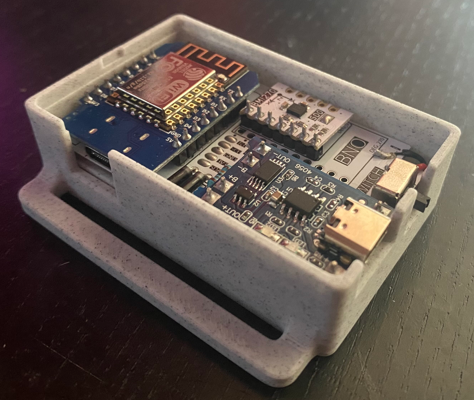
Image: Meia
- Customisable, see the Github for more information on ordering and assembly.
- PCB, see Github for more details.
- LSM6DSR, LSM6DSV, ICM-45686, BNO085
- Some community made adaptations/modifications.
- Specific components, battery sizes and switch types.
Sorakage's CheeseCake PCB Case
This is a recommended case for new builds.
Very delicious cakes, designed by Sorakage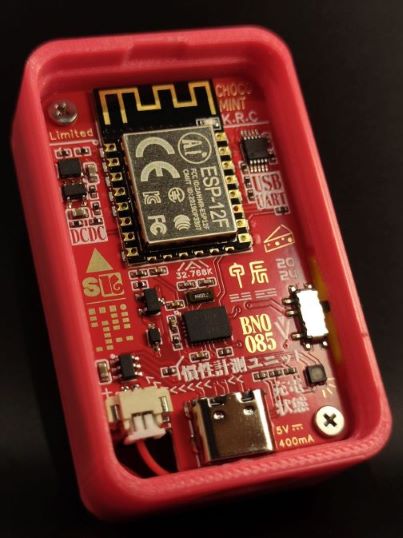
Image: Sorakage
- Customisable, see the Github for more information.
- PCB, see Github for more details.
- BMI-160, BMI-270, BNO085, LSM6DSVTR, ICM-42688
- A popular choice with a good variety of community made adaptations/modifications, mainly for bigger batteries.
- Specific battery sizes (803035 or 903035)
Gorbit99's Tiny-Slime PCB Case
A tiny and cheap module based SlimeVR tracker design by Gorbit99
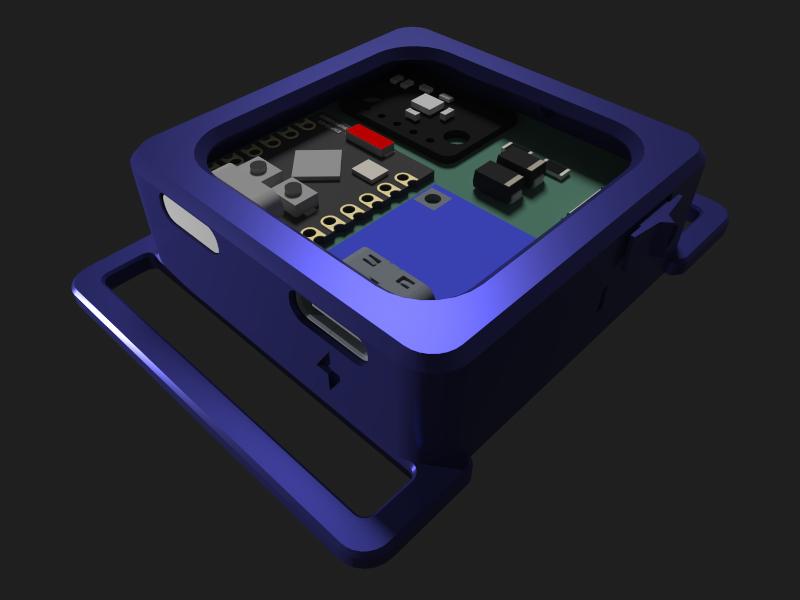
Image: Gorbit99
- Customisable, see the Github for more information.
- PCB, see Github for more details.
- LSM6DSR, LSM6DSV, ICM-45686
- Some community made adaptations/modifications.
- The antenna is only usable within the same room.
- Specific battery size, IMUs, MCU, power board.
ZRock35's Tiny-Official SlimeVR PCB Case
A remix of Gorbit99's TinySlime case for the Official SlimeVR PCB with adapted version of Pixel's clip to fit it onto!
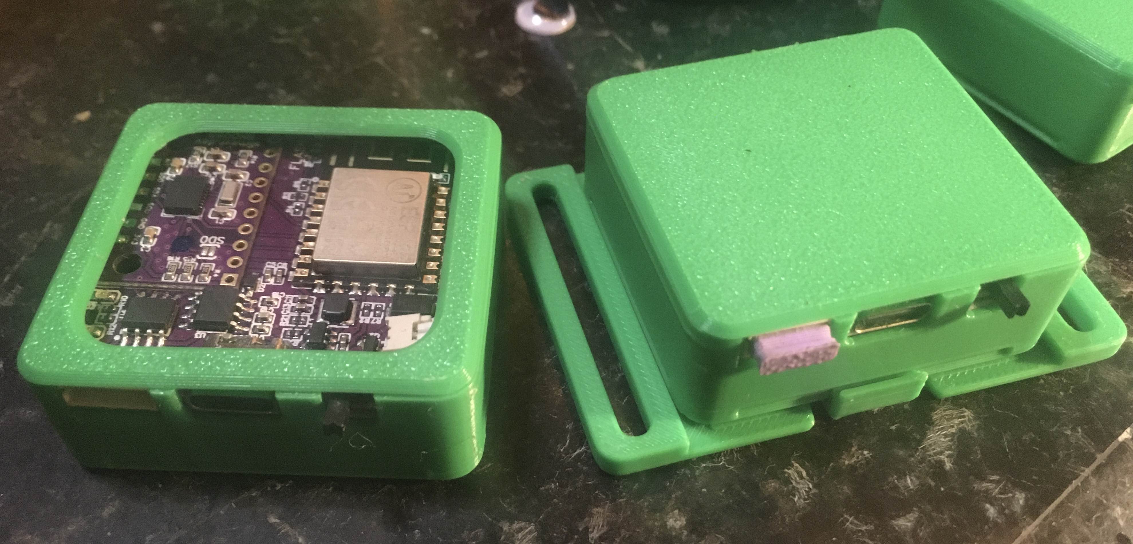
Image: ZRock35
- Very simple and tiny PCB case, designed to fit the Official SlimeVR PCB and battery with no modifications needed.
- Open or closed top option, with clip backplate allowing for easy removing.
- BNO085 Official PCB
- Official SlimeVR standard battery.
Frozen Slimes V2
Design by artemis/frosty

- Supports most IMU's
- 18650 LiIon Battery.
Historical/Obsolete Case Designs
These cases are not recommended for new builds due to size, internal geometry, or reliance on no longer recommended or supported DIY configurations.
Shine Bright's Hyperion PCB Case
Not a recommended case for new builds.
Modified Hyperion design by Shine Bright, based from Smeltie's original Hyperion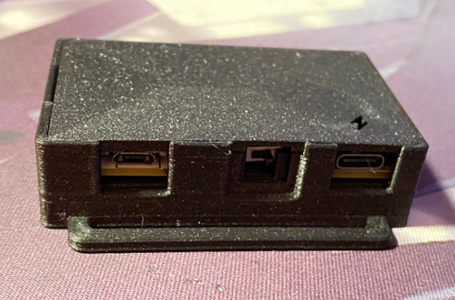
Image: Shine Bright
- Customisable, see the Github for more information.
- PCB, see Github for more details.
- LSM6DSR, LSM6DSV, ICM-45686, BNO085
- Many community made adaptations/modifications.
- Specific battery sizes and switch types.
The Hyperion
Not recommended for new builds.
Design by Smeltie
- Customisable, see the Github for more information.
- D1 Mini.
- MPU6050, MPU9250 & BNO085.
- Countless community made adaptations/modifications.
- Various battery sizes and switch types.
The Pucirion
Not recommended for new builds.
Hyperion case edit by Krysiek, Original Hyperion by Smeltie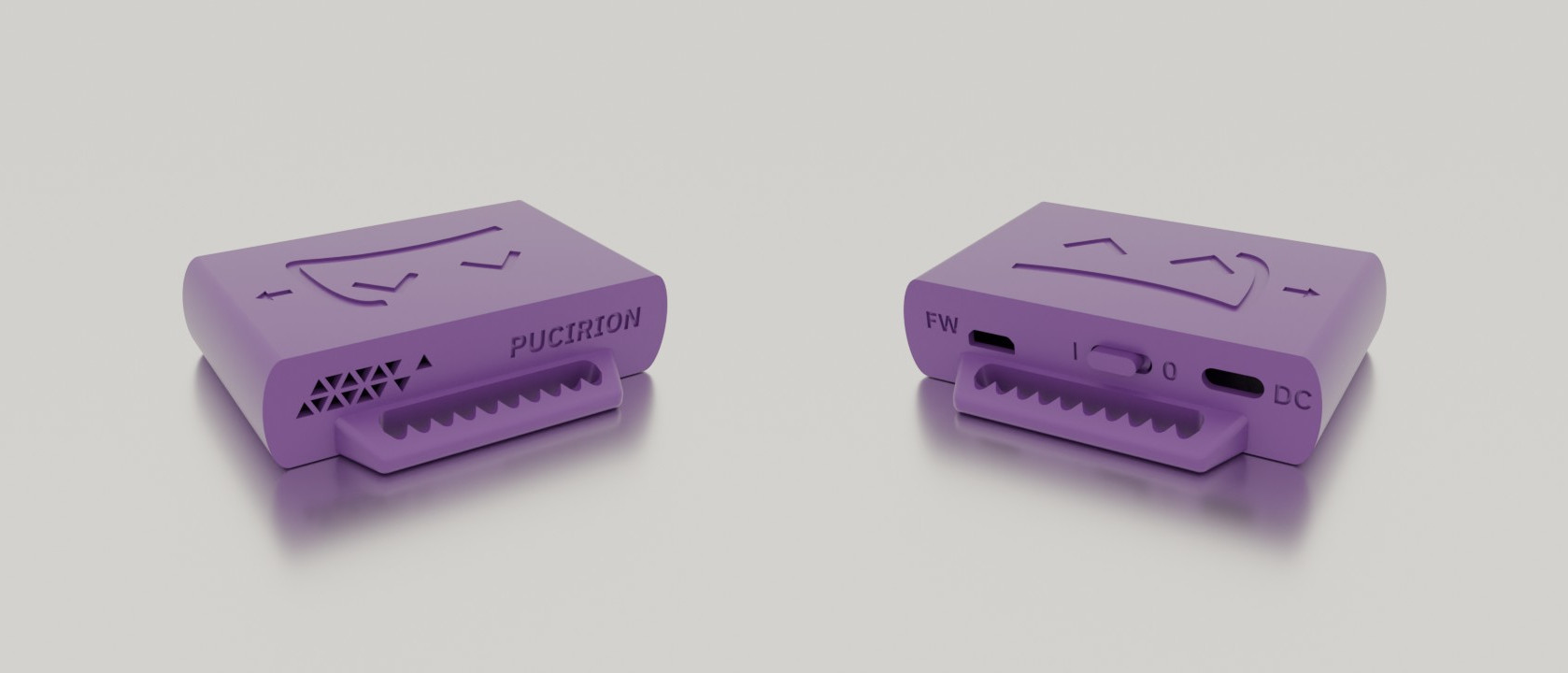
- Stronger handles with teeth that hold the strap, smaller, access to MicroUSB port, redesigned vent. See the Github for more information.
- D1 Mini.
- MPU6050, MPU9250 & BNO085.
- Pucirion repository link has only modified case STL files, full instructions are on the Hyperion repository.
Flexible TPU Case
Not recommended for new builds.
Design by ShoryuKyzan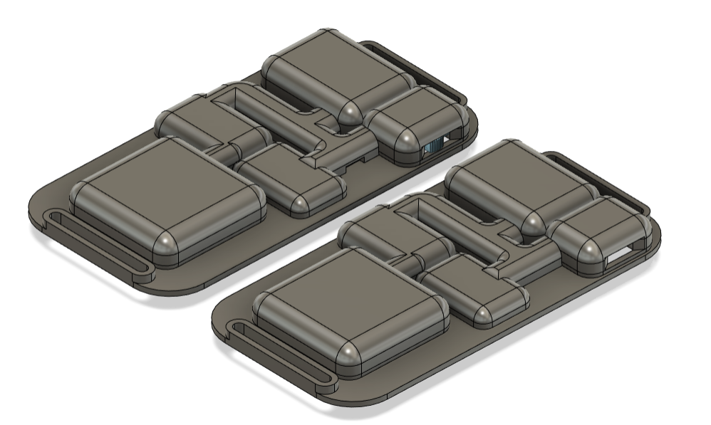
- SlimeVR case printed with TPU filament designed to flex in 3 places, be thin and form fitting. See the Github for more information.
- NodeMCU D1 Mini v3 USB-C (with diagonal corners, not holes at edges).
- BNO085.
- 804040 Battery.
- Additional details, components list and instructions on the repository.
Slidey-Slimes
Not recommended for new builds.
Design by punt-cuncher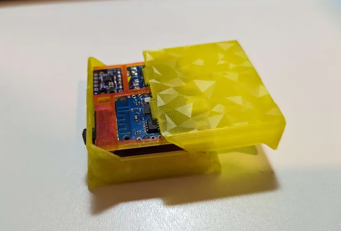
- Easy to assemble, fairly compact sliding case design. No need for screws or glue, just solder together, slide assembled tray into case with satisfying snap.
- D1 Mini 4.0
- BMI160, BMI270, BNO085 (SlimeVR store version).
- 804040 Battery or smaller.
- Additional details, components list and instructions on the repository.
Candy-Case
Not recommended for new builds.
Design by ManicQuinn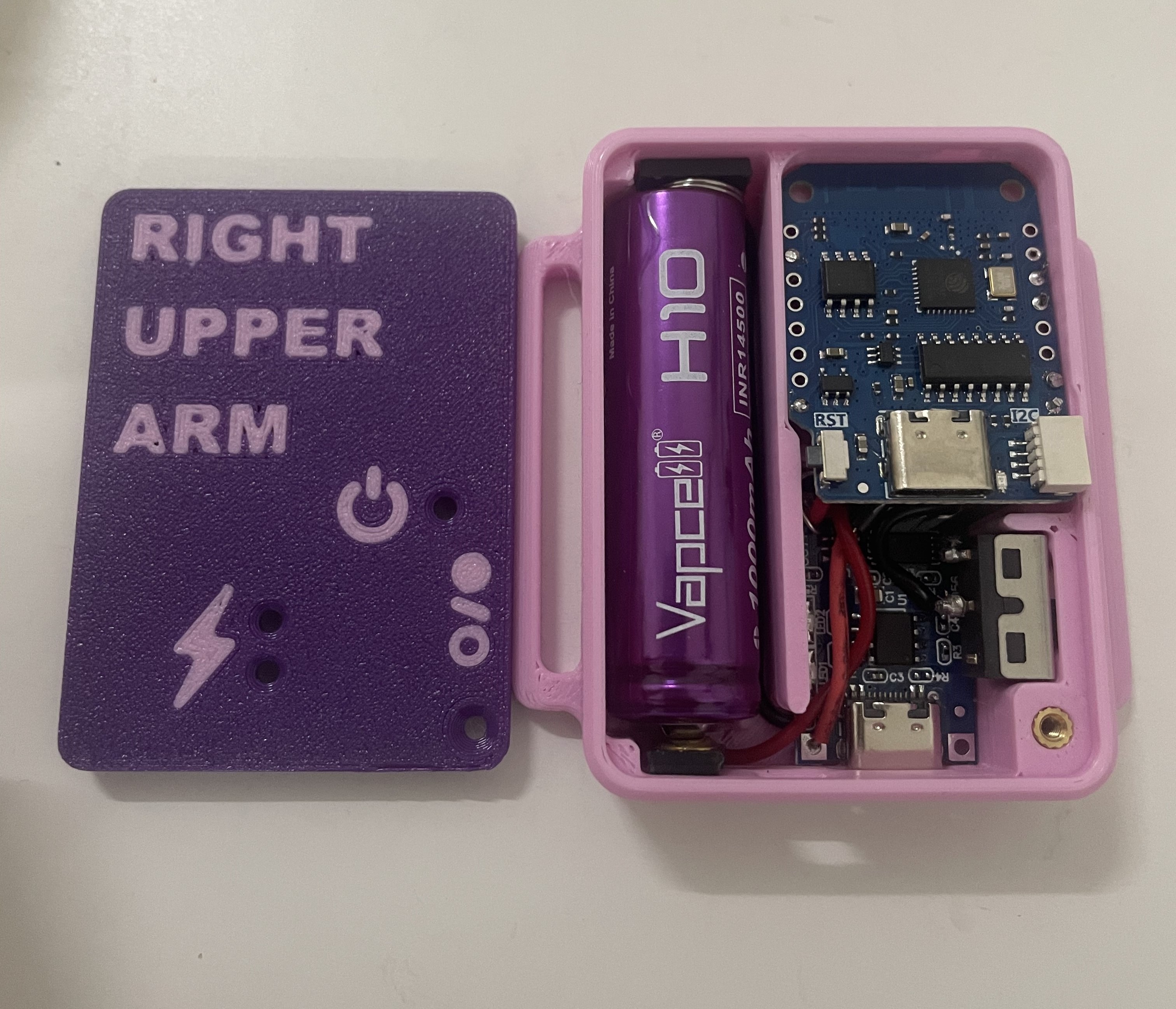
- Non-PCB case design, optimized for being compact while using breakout boards.
- D1 Mini 4.0
- BMI160, BMI270
- 14500 Lithium Ion Battery.
- Additional details, components list and instructions on the repository.
Zaku² Case
Not recommended for new builds.
Design by Tom Yum- Wemos D1 Mini.
- TP4056 Type-C charge board.
- MPU6050.
- 804040/BP-5M Battery.
Hexaeder
Not recommended for new builds.
Design by MaddesJG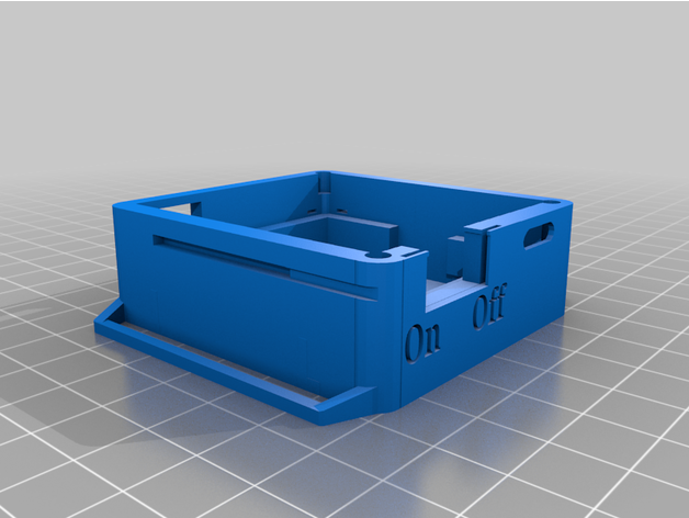
- Wemos D1 Mini.
- MPU9250 or MPU6050.
- 804040 Lip Battery.
Red's Case
Not recommended for new builds.
Design by Red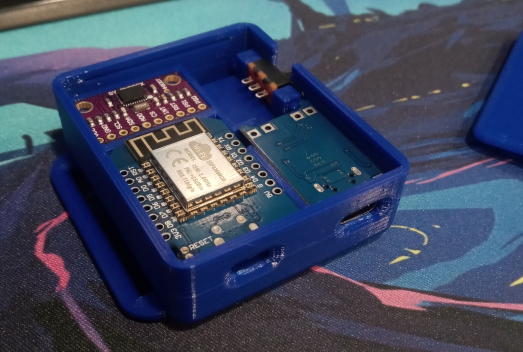
- D1 Mini.
- TP4056 Type-C charge board.
- BNO08x's.
- 783448 1200mAh LiPo.
SlimeVR Hello
Not recommended for new builds.
Design by Guiguig
- Wemos D1 Mini ESP8266.
- SPDT 1P2T Slide Switch.
- BNO085.
- 18650 Battery.
QuantumSlime
Not recommended for new builds.
Design by QuantumRed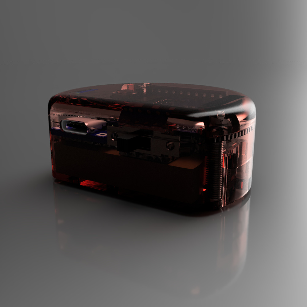
- WeMos D1 Mini.
- SS-12F15(VG6) Micro Slide Switch.
- GY-BNO08X.
- 803040 3.7V 1000mAh Li-Po.
Sauce Boss's Case
Not recommended for new builds.
Design by Sauce Boss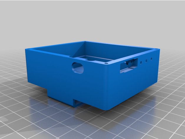
- ESP8266 NodeMCU.
- 2 Pole switch.
- BNO08x.
- 2000mAh battery.
SlimeVR Compact Case by Twidge
Not recommended for new builds.
Design by Twidge
- D1 Mini ESP microcontroller.
- 7mm x 3mm x 8.3mm panel switch.
- BNO08x.
- 503450 1000mAh lithium-ion cell.
Arcturus by Lixulia
Not recommended for new builds.
Design by Lixulia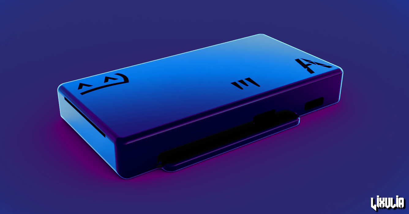
- D1 Mini ESP microcontroller.
- DPDT 2P2T Power Switch.
- BMI160 or BMI270.
- TP4056 USB-C charging module.
- 804040 1200mAh lithium ion cell.
Minted Arcturus by Rosdayle
Not recommended for new builds.
Base design by LixuliaModified, refined and with a few feature additions by Rosdayle
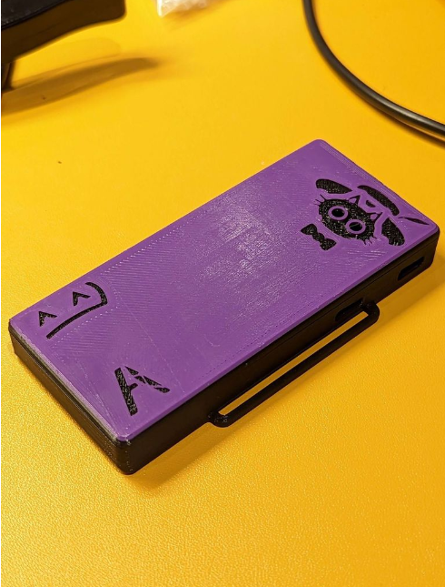
- D1 Mini ESP microcontroller.
- DPDT 2P2T Power Switch.
- BMI160 or BMI270.
- TP4056 USB-C charging module.
- 603450 1100mah lithium-ion cell or Smaller than 51x34x6mm.
- Go pro style chest harness.
SlimeX-FDM
Not recommended for new builds.
Design by Yasu3D
- Wemos D1 Mini V4 Wifi Board
- TP4056 USB-C Charger Board
- SS22F32 Switch
- BMI160 IMUs
- 804040 Li-Po Batteries
- 28AWG stranded silicone wire
SlimeCon
Design by Strnadik
- Thin, Joy-Con–sized form factor
- Custom quick-solder PCB
- Compatible with widely available Joy-Con velcro pouches
- TP4056 USB-C charging module
- Wemos D1 Mini ESP-12 Wi-Fi board
- MSK12C02 slide switch
- Supports Meia’s and Deyta’s LSM6DSR / LSM6DSV IMUs
- 1000 mAh 102050 LiPo battery
- Includes battery sensing and charge-and-play functionality
JSG Modular Cases
Design by Jaime Shirazi Games
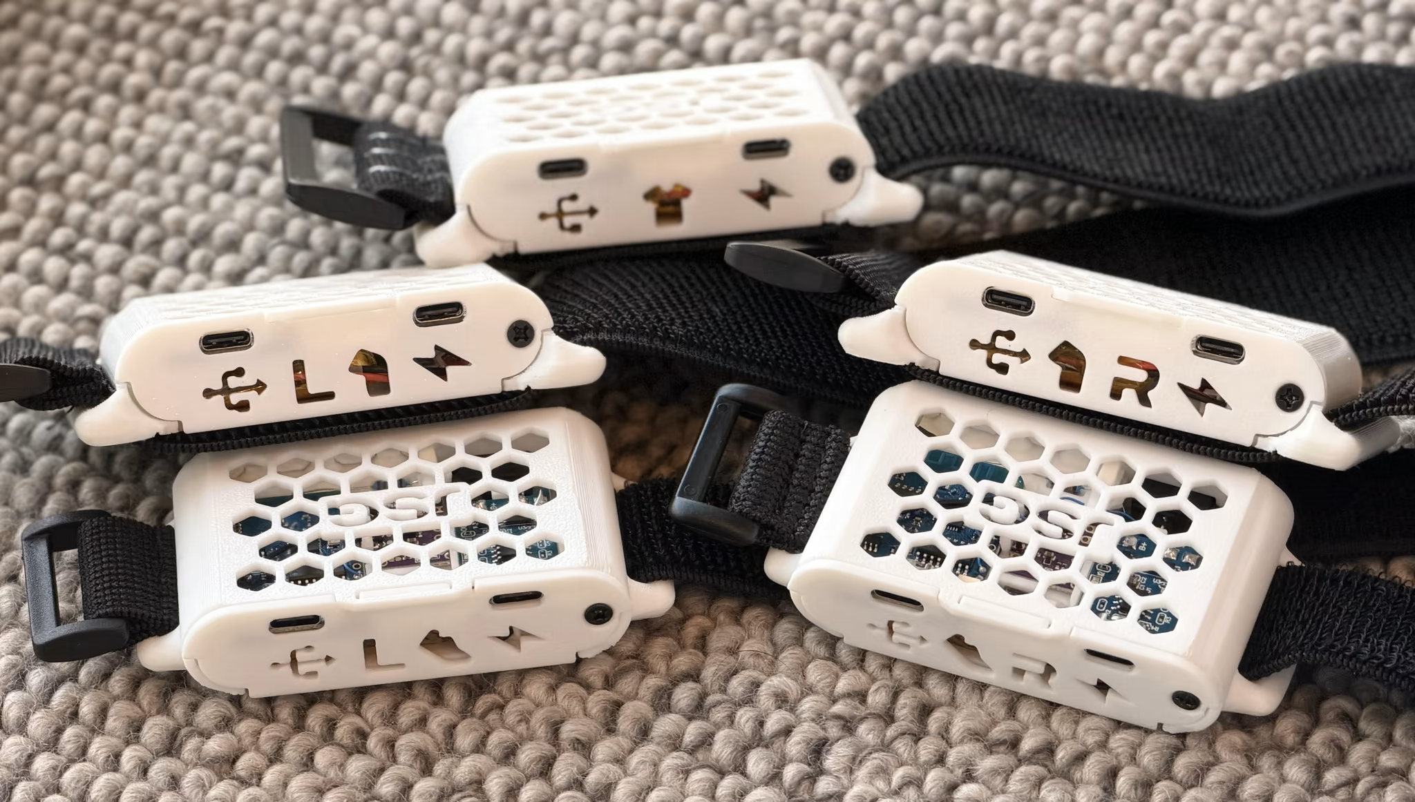
- D1 Mini V4.0.0
- ICM-45686 + QMC6309
- USB-C TP4056
- Modular design to easily swap labels and shell (different strap sizes)
- Designed without PCB
- Case prints fast on standard 0.4mm nozzles with PLA
- Instructions for assembly on GitHub
Thanks to the community for being so awesome and creating so many designs!
Tracker Schematics
SPI is the preferred protocol due to its better performance and energy efficiency. As a result, I2C may eventually be phased out and might not be supported in future firmware updates. Note that the magnetometer is not yet available over SPI.
Wemos D1 Mini
- IMUs ranked from best - worst
- - Currently the best widely available IMU and cheaper than LSM6DSV.
- - Very good and slightly cheaper than BNO085.
- - Decent and a little cheaper than ICM-45686 and LSM6DSV. Experimental.
- - Very good, but expensive $$$. Not recommended.
- - Adafruit version of BNO085. Not recommended.
- - Performs slightly better than BMI160. Still terrible. DO NOT USE!
- - Very cheap, and with equally low performance. DO NOT USE!
- - Cheap and worse than BMI160. DO NOT USE!
- - Worse than BMI270 and plagued with fakes. DO NOT USE!
- - Experimental cheaper MPU9250 equivalent. DO NOT USE!
- - Allows for a second motion sensor to be connected.
- - The device is able to sense the battery life remaining using a 180k resistor.
- - Allows for usage even when charging, and is a recommended safety measure.
 Note: If you are using the charge diodes the grey band goes on the side represented by the tip of the arrows in the diagram above.
| Label | GPIO | Input | Output | Description |
|---|---|---|---|---|
| A0 | ADC0 | Analog Input | No | For analog input from 0 to 3.3v and no output. |
| RX | GPIO3 | Yes | RX pin only | High at Boot. |
| TX | GPIO1 | Tx pin only | Yes | High at Boot. |
| D0 | GPIO16 | No interrupt | No I2C, PWM | Used to wake up chip from deep sleep, High at Boot. |
| D1 | GPIO5 | Yes | Yes | Often used as SCL |
| D2 | GPIO4 | Yes | Yes | Often used as SDA |
| D3 | GPIO0 | Pulled up | Yes | Connected to Flash button |
| D4 | GPIO2 | Pulled up | Yes | Connected to built-in LED, High at Boot. |
| D5 | GPIO14 | Yes | Yes | SCLK pin for SPI interface |
| D6 | GPIO12 | Yes | Yes | MISO pin for SPI interface |
| D7 | GPIO13 | Yes | Yes | MOSI pin for SPI interface |
| D8 | GPIO15 | Pulled to ground | Yes | CS pin for SPI interface |
Cable layout recommendation for auxiliary tracker
Note that while schematics show SDA and SCL running adjacent to each other, make sure that they are not physically adjacent when running in the auxiliary tracker cable. This is to avoid crosstalk and ensure stable operation of both trackers when cabled and allow the extension to safely reach more than 80cm.
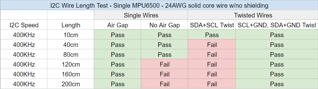
If you are using a ribbon cable or similar layout, use the following cable layout as a reference:
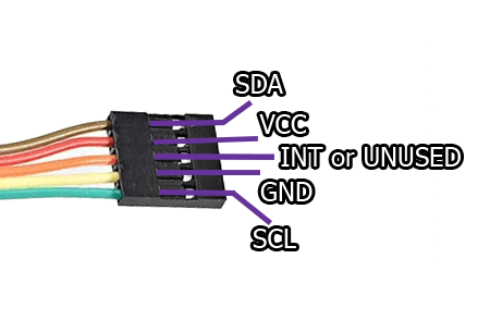
If you are using a twisted pair cable or similar layout, use the following cable layout as a reference:
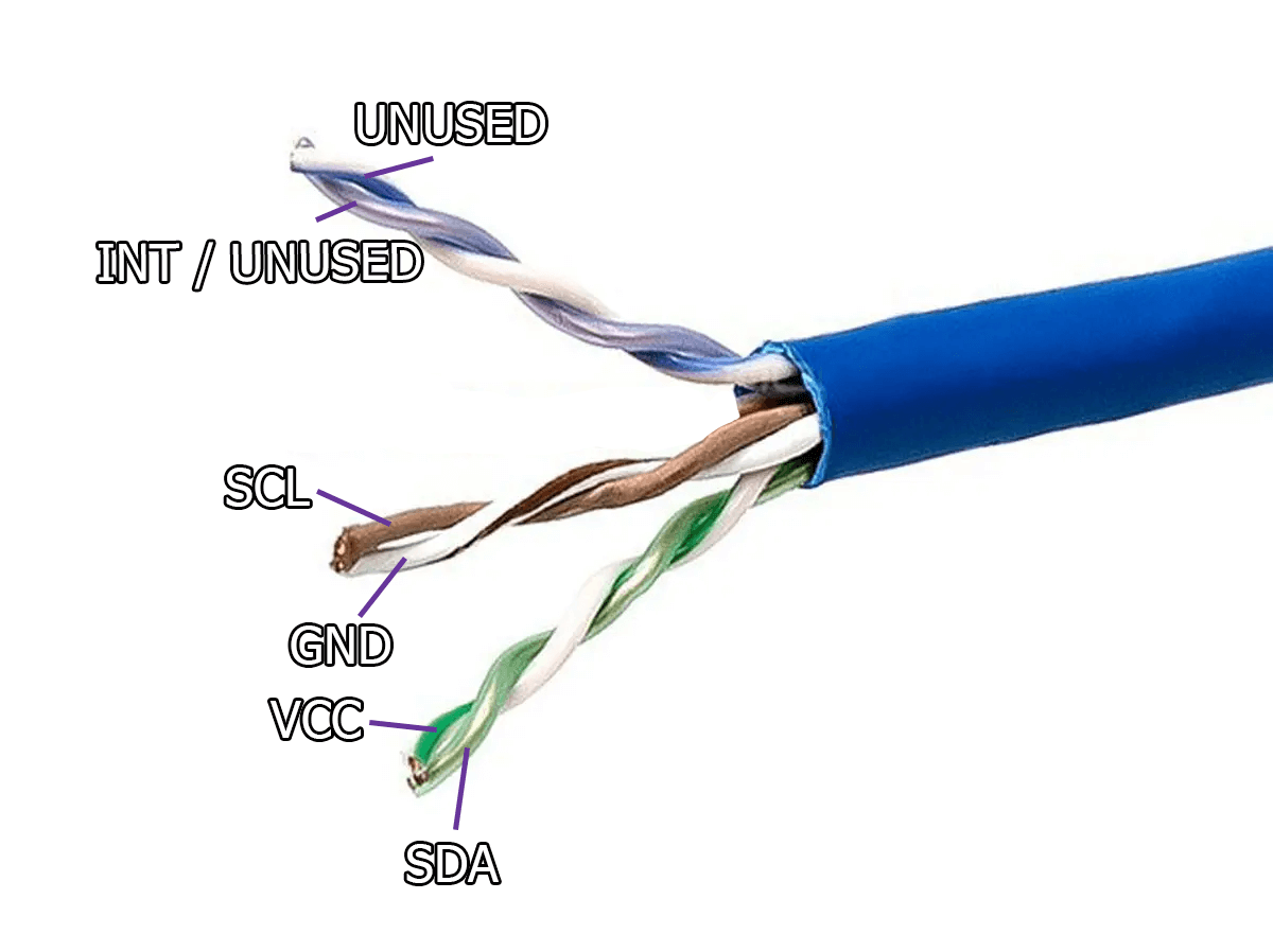
Code put together by Carl (https://github.com/carl-anders), with images made by Lune#0241, nwbx01, Meia, Aed and Reclusious#2022 thanks to the help of the whole DIY community. Doc page integration by emojikage. Edited by calliepepper, Aed, and Amebun. Thanks to snapchat_hotdog for the testing on the extension lengths.
IMU Comparison
This page is built on large amounts of community feedback, compared against a community survey, alongside side-by-side IMU tests conducted by various community members.
Rating Criteria
We rank these chips in the following categories: Reset Time, Cost, Availability, and Build Quality. Reset time (also referred to as drift time) can be described as the time it takes for the tracker to lose tracking accuracy on the yaw axis due to accumulated IMU error, often requiring a Yaw Reset to regain tracking accuracy.
These factors are meant to give a quick indication as to what to expect from various IMUs; your mileage may vary. For clarification purposes: If two out of ten chips or breakout boards are dead on arrival or die during early use, we refer to that as poor build quality.
Table of Contents
- IMU Tier Rankings
- Additional Info
- What's the difference between an IMU with a magnetometer (9 DOF) and an IMU without a magnetometer (6 DOF)?
- How can I check if I have an acceptable magnetic environment?
- My app shows around X uT, is that okay?
- What determines a "poor magnetic environment"?
- Does magnetic interference cause drift?
- Can I still use my IMU with a magnetometer if I don't have a stable magnetic environment?
- IMU Calibration
IMU Tier Rankings
Ordered from best to worst with the current firmware.
| IMU Model | Tier | Typical Price (USD) | Notes / Best For |
|---|---|---|---|
| 🟢 ICM-45686 | Superior | ~$6.70 | Best currently available. Reliable, accurate, and stays accurate the longest |
| 🟢 LSM6DSV | Superior | ~$8.93 | Great, but rarely in stock and expensive when they are |
| 🟢 LSM6DSR | Affordable | ~$3.35 | Recommended budget pick |
| 🟠 LSM6DSO | Legacy | Varies | Not recommended, few ready-made SlimeVR-compatible options |
| 🔴 BNO085 | Poor | Varies | Discontinued, hard to find, unreliable tracking, expensive |
| 🔴 BMI270 | Poor | Varies | Very poor tracking and loses accuracy quickly |
| 🔴 ICM-42688 | Poor | ~$8 | Prone to temperature-based drift |
| 🔴 ICM-20948 | Poor | ~$15 | Prone to drift, few SlimeVR-compatible options |
| 🔴 BNO055 | Poor | ~$38 | High drift, not competitive |
| 🚫 BMI160 | Avoid | ~$1.50 | High DOA rate, outdated, tracks extremely poorly |
| 🚫 MPU9250 | Avoid | ~$7 | High drift, counterfeits, poor tracking |
| 🚫 MPU+QMC5883L | Avoid | ~$2.50 | High drift, complex wiring, poor tracking |
| 🚫 MPU6500 | Avoid | ~$1 | High drift, high failure rate, poor tracking |
| 🚫 MPU6050 | Avoid | ~$1.04 | High drift, high failure rate, poor tracking |
🟢 Recommended IMUs
These IMUs are recommended choices for new SlimeVR tracker builds.
🟢 ICM-45686
ICM-45686 is a very good IMU for DIY SlimeVR. It performs slightly better than LSM6DSV and much better than BNO085, but at a lower price. It can be purchased directly from the SlimeVR store.
| Reset Time | Cost | Availability | Build quality |
|---|---|---|---|
| 45-60 min | ~$6.70 | Sufficient | Great |
| Pros | Cons |
|---|---|
| Accurate | More expensive than alternatives |
| Reliable | |
| Smooth |
🟢 LSM6DSV
LSM6DSV is a very good IMU for DIY SlimeVR. It seems to perform just as well as the BNO085, but at a lower cost.
| Reset time | Cost | Availability | Build quality |
|---|---|---|---|
| 45-50 min | ~$8.93 | Insufficient | Great |
| Pros | Cons |
|---|---|
| Accurate | Expensive relative to other IMUs |
| Reliable | Is rarely in stock |
| Smooth |
🟢 LSM6DSR
LSM6DSR is a good IMU for DIY SlimeVR. It seems to perform a little worse than the ICM-45686, mostly in sensitivity, while being cheaper. Like the ICM-45686, this comes with the QMC6309 magnetometer built into the module.
| Reset time | Cost | Availability | Build quality |
|---|---|---|---|
| 25-30 min | ~$3.35 | Sufficient | Great |
| Pros | Cons |
|---|---|
| Cheap | Lower reset times |
| Accurate | Worse sensitivity |
| Smooth |
🟠 Acceptable IMUs, but better options exist
Not recommended: These IMUs are acceptable to use if no other option is available.
🟠 LSM6DSO
LSM6DSO has average drift times and there is no reliable seller for breakout boards. It is not recommended to purchase new trackers equipped with this IMU from a third-party SlimeVR seller. There are trackers with better IMUs available at the same price or lower.
| Reset time | Cost | Availability | Build quality |
|---|---|---|---|
| 25-35 min | Varies | Insufficient | Varies |
| Pros | Cons |
|---|---|
| Cheap | No breakout board available |
| Reliable | Lower reset times |
| Smooth |
🔴 Poor IMUs, generally not recommended
These IMUs are generally not recommended for new SlimeVR trackers.
🔴 BNO085
This is the IMU used in versions 1.0 and 1.1 of the official SlimeVR trackers. This IMU has been discontinued from the SlimeVR store, making it difficult to obtain or to estimate its price. It also suffers significantly from the stomp bug.
| Reset time | Cost | Availability | Build quality |
|---|---|---|---|
| 45-60 min | Varies | Insufficient | Excellent |
| Pros | Cons |
|---|---|
| Accurate | Expensive |
| Reliable | Big |
| Smooth | Difficult to obtain at a good price |
| Very misleading AliExpress listings |
🔴 BMI270
BMI270 has well below average drift times, and there are no reliable sources for SlimeVR-ready boards. It is not recommended to purchase new trackers equipped with this IMU from a third-party SlimeVR seller. There are many trackers with better IMUs available at the same price or lower.
| Reset time | Cost | Availability | Build quality |
|---|---|---|---|
| 10-20 min | Varies | Insufficient | Varies |
| Pros | Cons |
|---|---|
| Cheap | No breakout boards available |
| Reliable | Lower reset times |
| Smooth |
🔴 ICM-42688
ICM-42688 is currently not recommended for new SlimeVR trackers. While it is a newer IMU, it is temperature sensitive and drifts fairly quickly.
| Reset time | Cost | Availability | Build quality |
|---|---|---|---|
| 25 - 30min | ~$8.00 | Sufficient | Varies |
| Pros | Cons |
|---|---|
| Cheap | Temperature sensitive drift times |
| Smooth | Expensive compared to other options |
| Accurate |
🔴 ICM-20948
The ICM-20948 is a relatively modern chip. While early testing results are promising, the chip has not yet seen enough real-world use to draw conclusive results.
There are quite a few variants of the ICM-20948, most of which operate at 3.3v.
- Pimoroni ICM-20948: Requires cutting a bridge on the back to change the I2C address.
- Adafruit ICM-20948: Requires soldering a bridge on the back to change the I2C address.
- SparkFun ICM-20948: Also requires soldering a bridge to change the I2C address.
- GY-912: Requires bridging SD0 to GND to change the I2C address.
- CJMCU-20948: Operates at 1.8V and is not recommended. It requires both a 1.8V linear voltage regulator and a logic level converter to function.
| Reset time | Cost | Availability | Build quality |
|---|---|---|---|
| 15 - 60 min | ~$15 | Insufficient | Good |
| Pros | Cons |
|---|---|
| Accurate | |
| Reliable | Sensitive to bad magnetic environments |
| Smooth | Availability is not guaranteed |
🔴 BNO055
Comment: Insufficient testing for an accurate description, but it cannot compete with the BNO085.
This is an earlier version of the BNO085 without stabilization firmware.
This chip lacks sufficient testing to provide a conclusive summary.
| Reset time | Cost | Availability | Build quality |
|---|---|---|---|
| 1 -10 min | ~$38 | Mediocre | Good |
| Pros | Cons |
|---|---|
| Affordable | High drift rate |
| Available | More expensive than the MPU6050 |
| Smooth | Failure rate inconsistent |
| Calibration on each start |
🚫 Avoid IMUs, do not use in new designs
Not recommended for use in new designs! You should absolutely avoid using these IMUs!
🚫 BMI160
BMI160 should not be used for new SlimeVR trackers. It is very outdated with almost all modern IMUs surpassing it in performance.
| Reset time | Cost | Availability | Build quality |
|---|---|---|---|
| 5 - 15min | ~$1.50 | Sufficient | Good |
| Pros | Cons |
|---|---|
| Cheap | Short drift times |
| Smooth | High DOA (Dead On Arrival) rate |
| Accurate |
🚫 MPU9250
Comment: Finding legitimate MPU9250s has become exceedingly difficult due to counterfeits and DOA IMUs. Buy at your own risk.
MPU9250 (currently run in several modes) is a newer installment of the MPU lineup.
| Reset time | Cost | Availability | Build quality |
|---|---|---|---|
| 10 - 40 min | ~$7 | Insufficient | Mediocre |
| Pros | Cons |
|---|---|
| Cheap | Very prone to counterfeit or DOA (Dead on Arrival) units |
| Smooth | Sensitive to bad magnetic environments |
| Reliable | Requires manual calibration for the first time |
🚫 MPU+QMC5883L
This is a highly experimental setup intended to approximately replicate the functionality of an MPU9250. Unlike other IMUs, which consist of a single PCB, this setup relies on connecting a magnetometer to an MPU6050 or MPU6500. That said, a breakout board that includes both an MPU6050 and an HMC5883L does exist: the GY-87. Both the QMC5883L and HMC5883L may be used; however, the QMC5883L may perform better.
| Reset time | Cost | Availability | Build quality |
|---|---|---|---|
| 10 - 40min | ~$2.50 | Sufficient | Mixed |
| Pros | Cons |
|---|---|
| Cheap | Very experimental |
| Smooth | Requires manual calibration the first time |
| Reliable | Sensitive to bad magnetic environments |
| Complex wiring |
🚫 MPU6500
MPU6500 is the middle ground of the MPU chips available. The drift time of this IMU may be a slight improvement over the MPU6050.
| Reset time | Cost | Availability | Build quality |
|---|---|---|---|
| 5 - 10 min | ~$1 | Sufficient | Mediocre |
| Pros | Cons |
|---|---|
| Affordable | High drift rate |
| Available | More expensive than the 6050 counterpart |
| Smooth | Failure rate inconsistent |
| Calibration on each start |
🚫 MPU6050
Comment: High failure rate. Order more than you need because of the higher failure rate, it is not uncommon to find 2 to 3 bad chips in a batch.
MPU6050 should be avoided. It loses accuracy within minutes and has poor motion sensitivity. It should not be used for any SlimeVR tracker.
| Reset time | Cost | Availability | Build quality |
|---|---|---|---|
| 1 - 5 min | ~$1.04 | Sufficient | Poor |
| Pros | Cons |
|---|---|
| Cheap | High drift rate |
| High availability | High failure rate |
| Calibration on each start |
Additional Info
What's the difference between an IMU with a magnetometer (9 DOF) and an IMU without a magnetometer (6 DOF)?
IMUs with a magnetometer, like a compass, use the Earth's magnetic field as a reference point to reduce gyroscope drift, however they require a stable magnetic environment or else they will perform erratically. IMUs without a magnetometer don't require a stable magnetic environment, but are prone to gyroscope drift over time due to being unable to differentiate sensor noise from actual movement, which means their rotational heading will slowly drift in the yaw axis over time. For SlimeVR's purposes, neither is inherently better or worse than the other. The ICM-45686, which is the IMU used in the official SlimeVR trackers, is currently used in 6DOF mode without a magnetometer.
How can I check if I have an acceptable magnetic environment?
You can check by using any magnetometer app that displays magnetic field strength in µT while walking around your playspace. You may want to check at varying heights, such as at chest level, waist level, and ankle level. One option available on both iOS and Android is Physics Toolbox Magnetometer. If you do use Physics Toolbox Magnetometer, you only need to pay attention to the total, not the X, Y, or Z components. Most phones include a magnetometer. If yours does not, you won’t be able to check directly, but you can still make educated assumptions based on known sources of magnetic interference.
My app shows around X uT, is that okay?
There’s no single 'safe' value; what matters is the fluctuation range. There is currently limited data to give an exact range, but a good baseline appears to be a fluctuation range of 5 µT or less. For example, 20-25 uT would be okay as would 40-45 uT, but a range from 20-40 uT would likely be too unstable to use.
What determines a "poor magnetic environment"?
Often objects made of steel or other ferromagnetic materials contribute most to a poor magnetic environment. Some common examples of things that might affect your magnetic environment include, but are not limited to: spring mattresses, radiators, PC cases, desktop speakers, or furniture made of steel. In most cases, the effect that these things will have extends about 15-30 cm (6-12 inches) and within that range may cause the IMU to rotate incorrectly. The size and amount of mass directly impacts the size of the affected area; a paper clip might only affect your IMU if it's directly next to it, whereas a steel bedframe might affect an area 15-30 cm (6-12 inches) away as previously mentioned. In most cases, depending on the size of your playspace, these issues of certain objects causing interference can be mitigated by avoiding or repositioning these items. Regardless, other factors such as the wiring, plumbing or rebar in your building could also affect your magnetic environment. These last few examples are harder to predict and illustrate why it's important to test with an app before assuming you might have a stable magnetic environment.
It's also worth mentioning that some controllers have magnets in them, either to hold the battery door closed or for the trigger. As such, placing your controller near a tracker with a magnetometer may cause it to spin slightly.
Does magnetic interference cause drift?
No, but you may still need to reset. When in an area of magnetic interference an IMU with a magnetometer will reorient itself the same way a compass will when put near a magnet; if you take the magnet away from the compass, the compass will return pointing towards magnetic North. As mentioned though, you may still find yourself needing to reset. For instance, if your bed has a steel bedframe you'll likely need to perform a reset so that your trackers are facing the correct orientation. If you then move somewhere else within your playspace you'll likely then need to reset once again.
Can I still use my IMU with a magnetometer if I don't have a stable magnetic environment?
This cannot be recommended. When run without the magnetometer, IMUs with magnetometers such as the MPU9250 and ICM20948 will perform much worse. That said, if for whatever reason you do want to use your IMU without the magnetometer, the MPU6500 or MPU6050 firmware can be used on the MPU9250 instead, and the ICM20948 can run in 6DOF mode.
Note that the IMUs mentioned in this subsection have more issues than just their magnetometer. Do not use them.
IMU Calibration
Some IMUs, such as the BMI270, BMI160, MPU9250, and MPU+QMC5883L, require manual calibration. This only needs to be performed once upon first setting up your SlimeVR tracker, however, you may need to perform the calibration multiple times before reaching satisfactory results. More information on how you would calibrate your IMUs can be found here.
Credits
Created by smeltie, edited by calliepepper, nwbx01, Aed, Amebun and Depact
A big thanks to everyone who took the time to fill out the survey.
DIY Straps Components
This page covers parts used to assemble DIY straps for both WiFi and Smol slime trackers.
Parts ratings are based testing and feedback from within the SlimeVR community.
Table of Contents
- Community Strap Designs for WiFi and Smol Slimes
- Tracker Placement
- Strap Parts
- 🎗️ Band
- 🔒 Buckle
- ↔️ Slide
- 🖨️ Buckles and Slides Printing Material
- Strap Sliding Troubleshooting
- Contributing
Community Strap Designs for WiFi and Smol Slimes
For information on existing community designs for WiFi Slime straps refer to Community DIY Straps, and Smol Community Straps for Smols straps.
Key differences affecting WiFi Slimes and Smol Slimes strap designs:
| Parameter | WiFi Slime | Smol Slime |
|---|---|---|
| Tracker Size | Bigger | Around 40x50mm (with strap mount) |
| Regular Strap width | 50mm | 30mm |
| Extension Trackers | Yes | No |
| Average Tracker Weight | 50g | ~10-15g |
Tracker Placement
Strap Parts
🎗️ Band
Band Materials
Elastic Band with Non-Slip Webbing
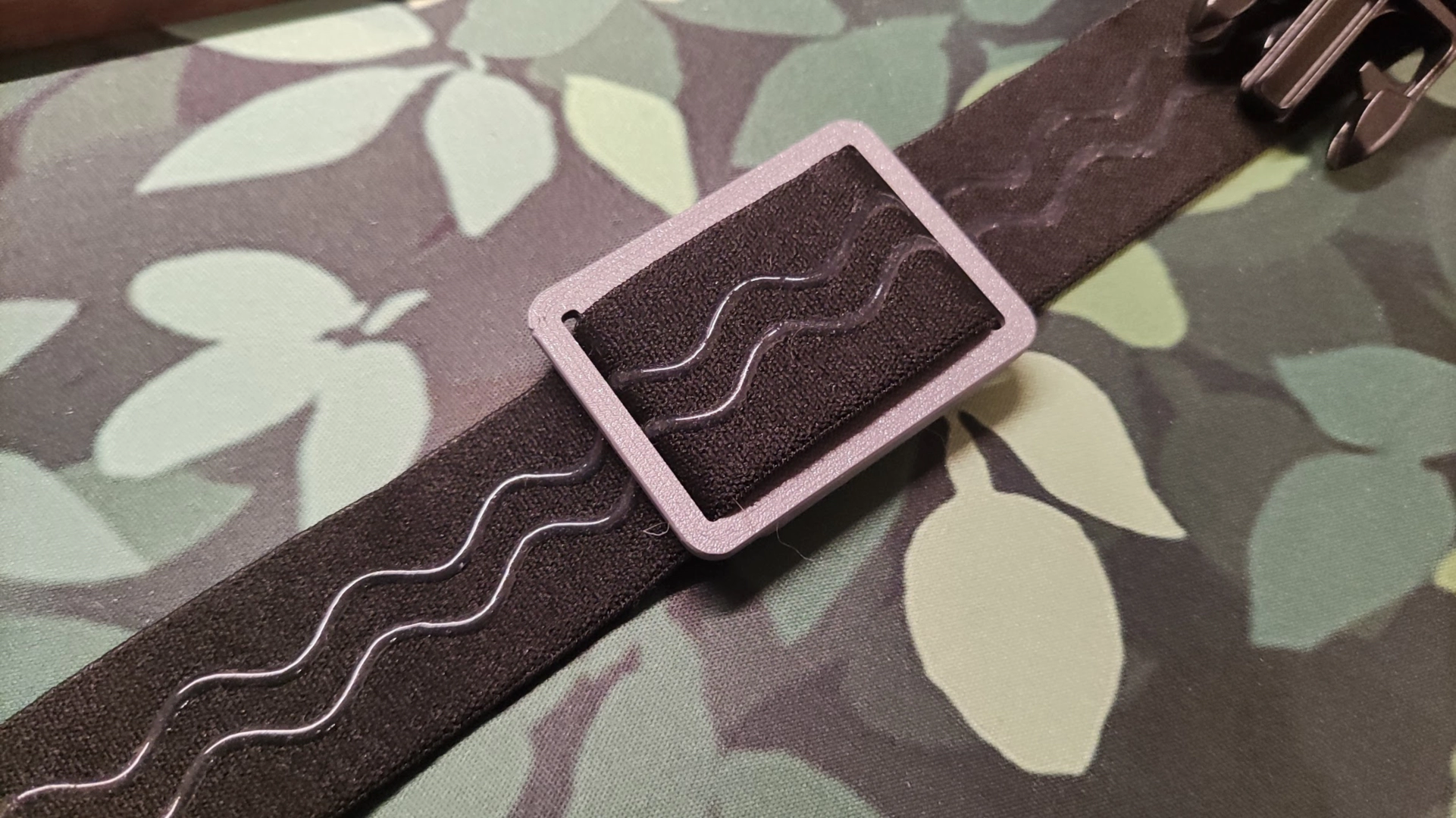
The foundation of most entry level DIY straps.
This elastic band with integrated non-slip silicone webbing provides better grip against skin compared to standard elastic and nylon, reducing tracker rotation and drift during movement.
Can be found by searching: Elastic Band With Non-slip Webbing.
| Pros | Cons | Link |
|---|---|---|
|
|
AliExpress |
Band Support
🟢 GoPro Chest Strap

A purpose-built harness for chest-mounted action cameras. When paired with a tracker mounting adapter, it provides excellent stability for chest trackers for minimal price. Ideal if you want a pre-made solution without custom sewing.
Can be found by searching: Chest Strap Mount Belt for GoPro.
| Pros | Cons | Link |
|---|---|---|
|
|
AliExpress |
Compression Knee Brace
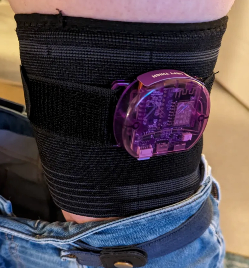
A ready-made support garment designed to stay firmly in place on the leg. The built-in compression and non-slip material make it an excellent choice for thigh tracker placement without requiring additional modifications. Contributed by Dean Ravencrest dot dog.
| Pros | Cons |
|---|---|
|
|
Measuring Band Length for Making Straps
What You Need
- Soft measuring tape
1. Measure Placement Areas
Wrap the band snug, not tight around each spot of tracker placement. Keep the band flat and level.
2. Add Allowance
Add 10 cm to each measurement. You can always cut down.
Some of the added length is needed to hold strap in place by buckles and slides.
3. Final Check
Bands should:
- Stay secure during movement.
- Not restrict circulation.
- Have 5 cm of adjustment.
Example:
5 meters of elastic band are generally enough to make 6 straps for an average man wearing European size XL.
🔒 Buckle
Buckle Tier Rankings
Ranking criteria:
- Ease of opening and closing on limb blindly - can you easily close it on limb without looking?
- Comfort while standing - does it dig in or feel bulky?
- Comfort while laying on it - Do you feel it while lying on it?
- Friction for band fragment it holds - does the band slip through?
- Tactile markers to help prevent twisted band locking, by telling where top and bottom is - can you orient it correctly by touch, when closing it?
🟢 Recommended Buckles
🟢 Brackles V2 30/38/50mm for Elastic Straps by RDTiel

| Pros | Cons | Width | Link |
|---|---|---|---|
|
|
30mm, 38mm, 50mm | Thingiverse |
🟢 Dovetail Strap Latch 30mm/40mm/50mm by MoDErahN

| Pros | Cons | Width | Link |
|---|---|---|---|
|
|
30mm, 40mm, 50mm | Thingiverse |
🟠 Acceptable Buckles, but Better Options Exist
🟠 Common AliExpress Plastic Buckle

| Pros | Cons | Width | Link |
|---|---|---|---|
|
|
30mm, 40mm, 50mm | AliExpress |
🔴 Poor Buckles, Generally Not Recommended
🔴 SlimeVR Straps Clip Hook Extended by Astrlx
 by Astrlx.webp)
| Pros | Cons | Width | Link |
|---|---|---|---|
|
|
50mm | Thingiverse |
🔴 Velcro Strap Quick Clip Hooks by Kurzaq

| Pros | Cons | Width | Link |
|---|---|---|---|
|
|
25mm, 35mm | Thingiverse |
↔️ Slide
Tri-glide Slide, a.k.a. Webbing Slide
A small but essential component for adjustable straps. This simple device consists of a rectangle with a dividing bar, creating two openings. The band threads through one opening and back through the other, allowing you to adjust strap tightness without sewing. Works best in combination with a primary buckle for maximum security.
Slide Tier Rankings
Ranking criteria:
- Comfort while standing - minimal bulk and pinching.
- Comfort while laying on it - smooth surface without sharp edges.
- Friction for band band it holds - secure grip without slipping.
🟢 Recommended Slides
🟢 30mm, Slide Buckle by Guidoo

| Pros | Cons | Width | Link |
|---|---|---|---|
|
|
30mm | Thingiverse |
🔴 Poor Slides, Generally Not Recommended
🔴 Keeper Loop
Keeper loop is fixed or movable loop that holds the loose end of the strap flat against the strap after it's buckled.
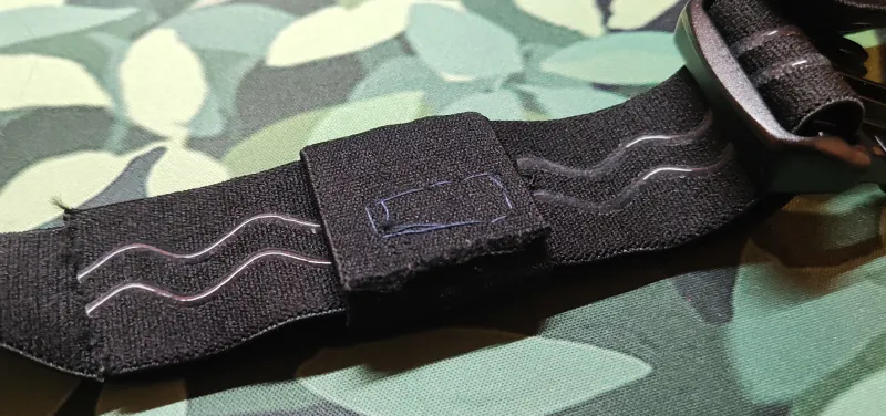
| Pros | Cons | Width | Link |
|---|---|---|---|
|
|
Flexible | N/A |
🖨️ Buckles and Slides Printing Material
🟢 Best Performance
🟢 PETG
- Strength: Good impact resistance, less brittle than PLA
- Durability: Holds up well to repeated use and sweat exposure; generally has stronger layer adhesion than PLA, which improves durability for buckles and other load-bearing printed parts.
- Print Settings: Print slightly hotter for best layer bonding. PETG typically requires little to no part cooling (reserve cooling only for bridges); lower print speeds and proper temperatures improve strength.
- Issues: PETG is hygroscopic — it absorbs moisture from air. Store and handle dry (use a dry box or dry filament before printing). Moisture causes increased stringing and print defects.
- Availability: One of the widely available FDM 3D printing materials
🔴 Breaks Apart from Active Usage over Time
Not recommended: These materials are acceptable to use if no other option is available. They have issues with properties critical for printing parts that work and last.
🔴 PLA+/PLA Pro
- Strength: Better than standard PLA
- Durability:🔴 Moderate; can crack under repeated stress
- Friction: Higher friction than PETG, slides may stick
- Issues: Brittle, heat sensitivity (hot rooms/sunlight)
🔴 Standard PLA
- Strength: Weakest option, prone to snapping
- Durability: 🔴 Poor for functional parts with repeated use, better not use
- Friction: Can work for slides but wears faster
- Issues: Brittle, especially in thin sections. Very bad for smol cases
- Availability: One of the most available FDM 3D printing materials
- Best for: Testing fit before printing in better material
Strap Sliding Troubleshooting
Straps slipping is one of the most common issues when making your own straps. This causes trackers to move and rotate, degrading tracking accuracy. For good tracking it is critical for your straps to not slide.
There are a few things you can try to prevent or minimize this issue.
Things to check:
- Material that is too flexible-stiffer materials with more grip resist sliding better.
- Your straps are too narrow/small. Wider straps distribute pressure more evenly and slide less.
Ideas:
- Add a few lines of hot glue on the strap for added grip on the skin-facing side.
- Use secondary straps to keep the trackers in place (like Tom Yum's design).
Contributing
Want to share your own DIY strap design, tip, or resource?
We welcome community contributions!
- How to contribute:
- Suggest changes, share your ideas and experience in the SlimeVR Discord -> Suggestions on strap improvements channel.
- Or, open a pull request on the SlimeVR Docs GitHub repository.
When contributing, please include clear photos, a description, and any relevant links or files. Your contribution helps make VR more accessible and easier to build for everyone!
Created by smeltie, tomyum3dp, fadetoblk27, and Depact
Community DIY Straps
This page contains strap designs for WiFi SlimeVR Trackers submitted by the community.
- This page is not a definitive or step-by-step guide to straps.
- It is meant to inspire you to create your own DIY straps.
- All examples shown are community-made or provided.
For community straps for Smol Trackers refer to Smol Community Straps.
Table of Contents
Common Components
For information on common strap components, 3D-printable buckles, and tracker placement, refer to DIY Straps Components
Community Strap Builds
Tom Yum's
Tom Yum's design involves sewing the velcro onto the strap, using it as the main mounting method for the tracker. This avoids the skin contact involved with using loops threaded through the strap.
These straps require the following materials:
- 105mm Elastic band
- 40mm Elastic band
- 20mm Elastic band
- Velcro Strips (Non-adhesive)
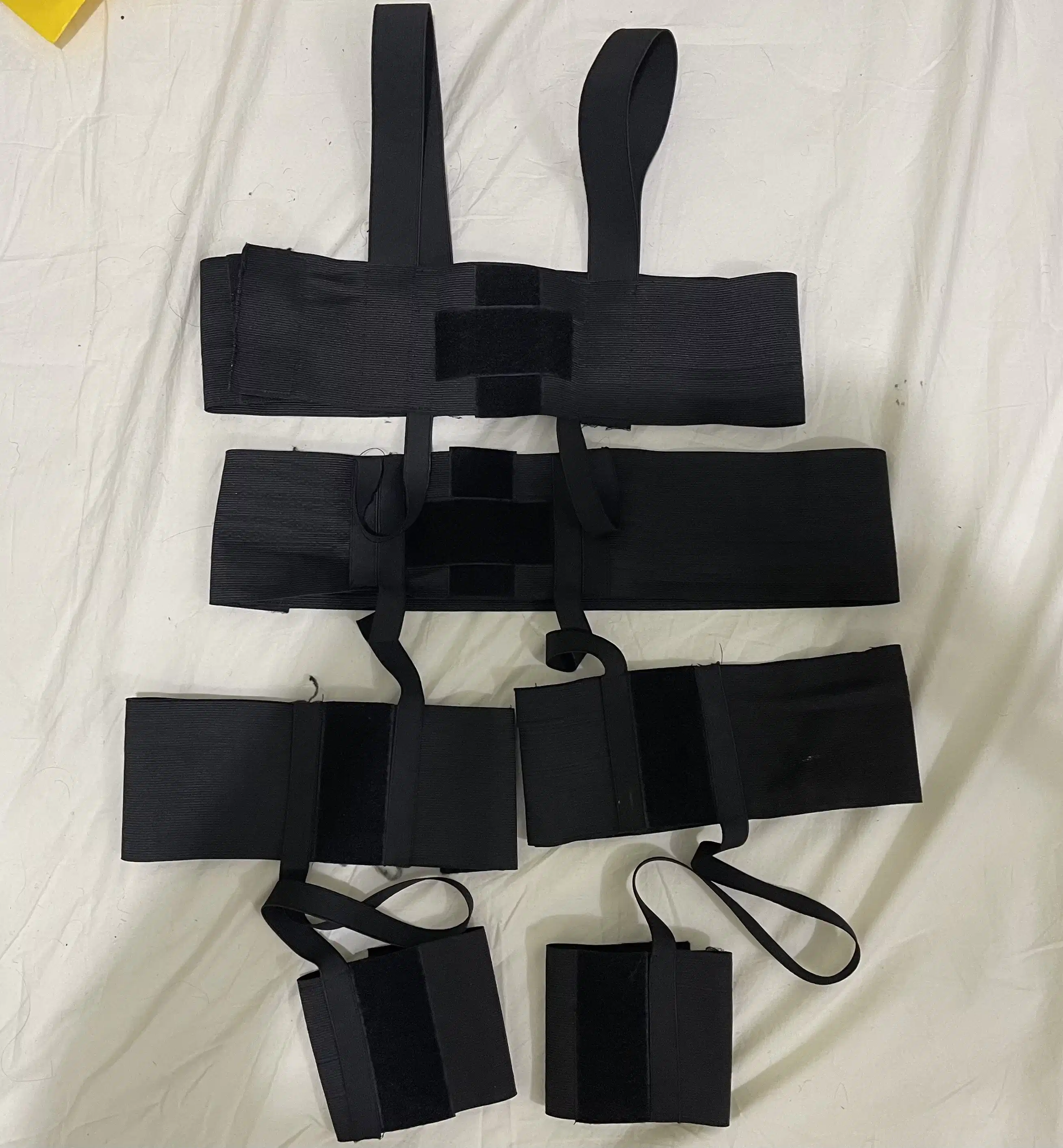
Fadetoblk27's
Fadetoblk27's setup uses slider buckles to secure the strap ends. While this build does not require sewing, it may be sewn together to improve durability.
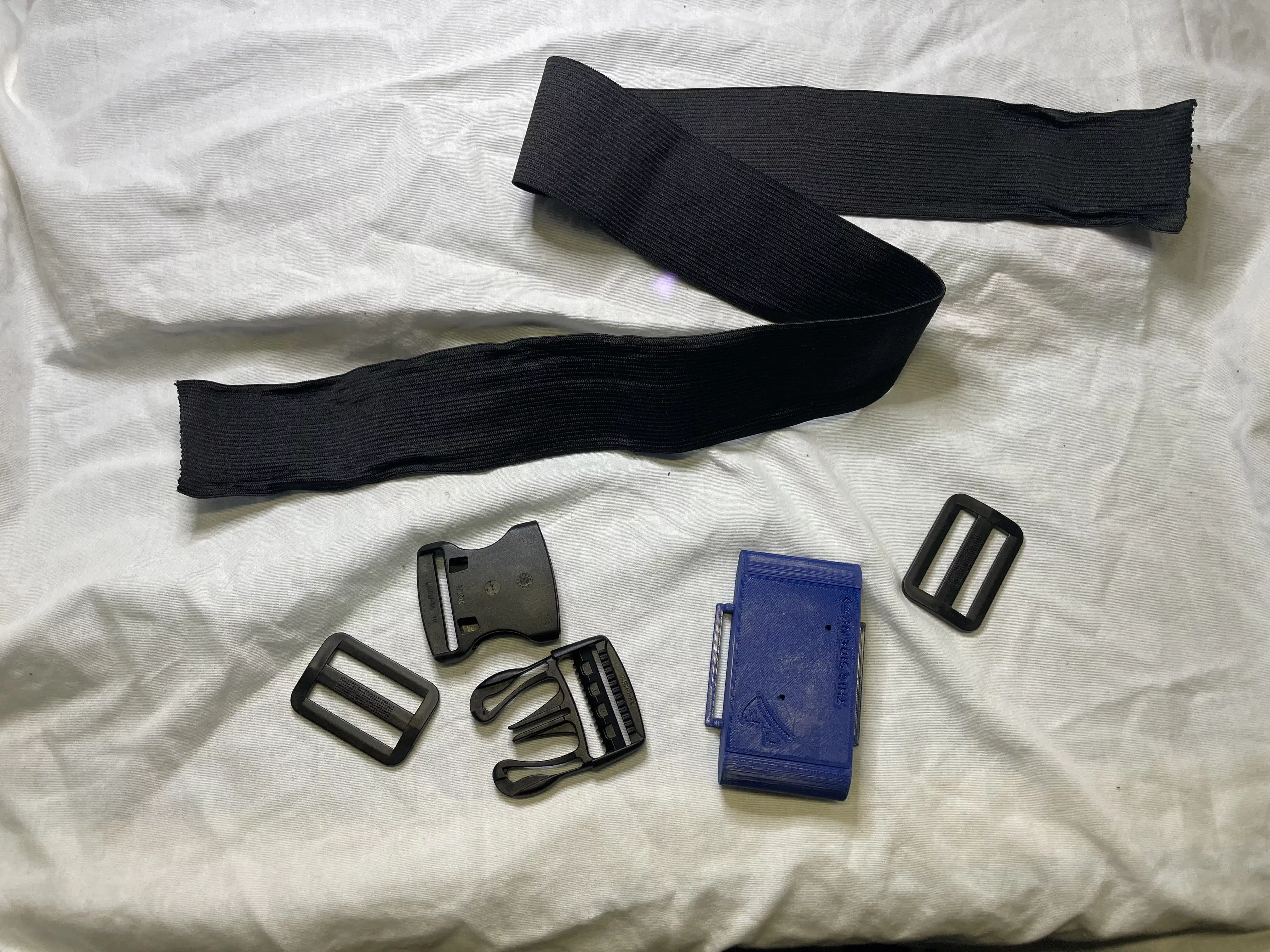
Materials used:
- Elastic band 50mm
- 50mm Buckles
- 50mm Slider Buckles
Instructions: Cut a strip of material to the desired length by wrapping it around the desired body part. Weave the strap through the normal buckle on both ends and instead of sewing the ends, weave them through the slider buckles (as seen in the picture). This allows the straps to be very adjustable and require no sewing. Sewing can still be done if the added strength/stability is desired.
Smeltie's
For Smeltie's straps, the material ELA1300 was used. Unfortunately not widely available outside the EU/UK. This material can be found at LeDuc (Europe) and various UK based stores. It is sometimes referred to as Elastic band for underwear/skirts. You can recognize it by the lack of longitudinal lines in the material (most elastic bands just have a few rubber threads along the length of the material).
These straps require the following materials:
- ELA1300 50mm Elastic band (Can be substituted)
- Velcro strips (Preferably without adhesive)
- 50mm buckles
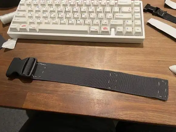
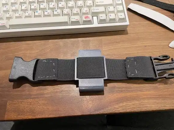
These straps have one closed end and one end with velcro.
Instructions Cut the strap to fit your body part, leaving extra length. Weave one end of the strap through one of the buckle halves, and sew it ~1 inch past the edge. Weave the other end through the other half of the buckle, but instead of sewing, attach a strip of velcro on either side. Fit the strap and test tightness before you sew the velcro in place. Once finished, you can make an exact replica for the opposite side of your body.
Contributing
Want to share your own DIY strap design, tip, or resource?
We welcome community contributions!
- How to contribute:
- Open a pull request on the SlimeVR Docs GitHub repository.
- Or suggest changes and share your ideas in the SlimeVR Discord -> Suggestions on strap improvements channel.
When contributing, please include clear photos, a description, and any relevant links or files. Your contribution helps make VR more accessible and easier to build for everyone!
Created by smeltie, tomyum3dp, fadetoblk27, and Depact
Uploading Tracker Firmware
The recommended way to flash the SlimeVR firmware onto your trackers is to use the DIY Firmware Tool built into SlimeVR.
Be sure to select the correct:
- Board Type
- Primary IMU (do not leave on
IMU_AUTO) - Secondary IMU (do not leave on
IMU_AUTO, remove if not using extensions)
For example, if you are building meowCarriers using ICM45686, without extensions, you will select:
- Board Type: Wemos D1 Mini
- Primary IMU:
IMU_ICM45686 - Secondary IMU: Removed
Alternatives
If you need to customize the firmware, you will need to compile and flash using PlatformIO.
This can be useful if you need to:
- Overclock the MCU
- Swap the primary and secondary IMU addresses
- Develop new firmware features
The following pages will walk you through the process of manually flashing your trackers. The guide assumes you have working and complete trackers, and are going to be using the PlatformIO approach. All screenshots are for a Windows-based system.
Setting up the Environment
This procedure will show how to prepare your system for uploading the firmware to your tracker.
1. Install Visual Studio Code
Download the latest Visual Studio Code and install it.
2. Install PlatformIO IDE
Once Visual Studio Code is installed, open it and install PlatformIO IDE for VSCode, an extension that will allow you to connect to the tracker, build and upload the firmware.
3. Install Device Drivers
Please note: these drivers will be automatically installed if you download and run the SlimeVR server.
For CH340 (NodeMCU v3, Wemos D1 Mini, and official SlimeVR trackers)
Download the CH341SER.EXE file from here, run it and follow installation instructions.
For CP210X (NodeMCU v2)
-
Download the zip archive with the drivers from silicon labs here.
For any other OS, the drivers can be found here.
-
Extract the files from the downloaded zip archive, then launch
CP210xVCPInstaller_x64.exe(CP210xVCPInstaller_x86.exeif you are using 32-bit Windows) and follow installation instructions.
4. Install Git Client
For Windows, you can download and install Git for Windows. If you have other OS, visit https://git-scm.com/downloads.
5. Choose a Firmware Version
Some hardware configurations may require different versions of firmware.
For most trackers, using https://github.com/SlimeVR/SlimeVR-Tracker-ESP.git is fine.
For MPU+QMC5883L trackers, you need https://github.com/deiteris/SlimeVR-Tracker-ESP.git.
6. Clone the Firmware Project
Make sure you close any current projects you have open or open a new window before moving forward with these steps.
-
Click the Source Control button, click on Clone Repository and enter the link to the firmware version you chose in step 5.
If you installed git while Visual Studio Code was open you may have to close it and re-open it first.
-
Once you have chosen a download location click the Open button that appears at the bottom right.
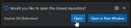
-
Click Yes, I trust the authors.
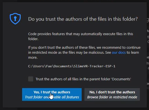
-
(MPU+QMC5883L only) Click the Source Control button, click on main and choose either qmc-mag-new or hmc-mag from the dropdown depending on whether you're using a QMC5883L or an HMC5883L.
Configuring the Firmware Project
In order to build SlimeVR firmware and upload it to your tracker, you need to configure the project to match your specific hardware configuration. To do this, you need to modify two files: platformio.ini and defines.h.
Table of Contents
1. Configuring platformio.ini
The platformio.ini file specifies the information about your MCU.
This file can be found in the root directory of the project:
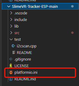
The contents of platformio.ini file should look as follows:
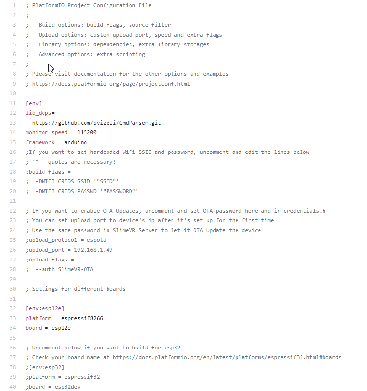
Select Your Hardware Settings
Monitor Speed
This field set your serial monitor speed in VSCode monitor_speed = 115200. Change this if your board datasheet and documentation suggest so, but the defaults should work.
For the platform and board fields, visit PlatformIO Boards documentation and find your board there. If it's not there, keep default ones or ask on SlimeVR Discord.
env
Important: Other env lines must be commented out with preceding semicolon (
;) character.
If you're using a board with an ESP8266, uncomment the following lines:
[env:esp12e]
platform = espressif8266
board = esp12e
If you're using a board with an ESP32, uncomment the following lines:
[env:esp32]
platform = espressif32
board = esp32dev
WiFi
If you're having problems with setting the wifi credentials through the server, you can hardcode your wifi credentials to firmware.
To hardcode your wifi credentials, uncomment the following lines and replace SSID and PASSWORD with your corresponding wifi credentials:
  -DWIFI_CREDS_SSID='"SSID"'
  -DWIFI_CREDS_PASSWD='"PASSWORD"'
If you are having problems getting the tracker to connect to your Wi-Fi, review these troubleshooting steps:
- If your wifi password contains the
%character, replace it with%%. - If your network SSID contains non-alphanumerical characters, the tracker could fail to connect
- The ESP8266 and ESP32 only support 2.4GHz network bands.
2. Configuring defines.h
The defines.h file specifies the information about your IMU and MCU.
This file can be found in the src directory of the project:
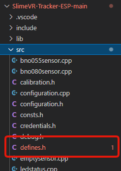
You can either edit the defines.h file manually or use the tool below to generate the contents of the file.
Configuring defines.h Automatically
Select how you built your SlimeVR tracker:
After selecting the settings above, you can either:
- Use the download button below and replace your defines.h file.
- Copy and paste from the text field below into your IDE (such as VSCode).
If you have used the above tool, you are finished with the defines.h file.
Configuring defines.h Manually
You can also configure the defines.h file manually instead of using the tool above. Before any changes to the file, the contents of defines.h file should look as follows:
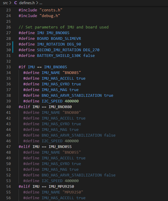
Select Your Hardware Settings
First you need to change these lines to define your IMU model and MCU:
// Set parameters of IMU and board used
#define IMU IMU_BNO085
#define BOARD BOARD_SLIMEVR
#define IMU_ROTATION DEG_90
#define SECOND_IMU_ROTATION DEG_270
#define BATTERY_SHIELD_130K false
Change the IMU Model
The following line defines which IMU is present:
#define IMU IMU_BNO085
To change IMU model, replace IMU_BNO085 with one of the following values depending on your IMU model:
IMU_BNO080
IMU_BNO055
IMU_MPU9250
IMU_MPU6500
IMU_MPU6050
IMU_BNO086
IMU_ICM20948
IMU_BMI160
IMU_BMI270
If you're using an MPU+QMC5883L, you would set your IMU as IMU_MPU9250. Bear in mind, you need to be using the QMC firmware for this to work, as the main firmware does not support the MPU+QMC5883L.
Change Board Model
The following line defines which MCU board is present:
#define BOARD BOARD_SLIMEVR
To change the board model, you must replace BOARD_SLIMEVR with one of the possible values:
- For most boards with ESP8266, set it to
BOARD_NODEMCU. For Wemos D1 Mini, you can useBOARD_WEMOSD1MINI. - For boards with ESP32, set it to
BOARD_WROOM32. - For other boards that don't follow the pinouts of any defined board, set it to
BOARD_CUSTOMand define the pins yourself.
Adjust IMU Board Rotation
The following lines define the rotation of your IMU boards:
#define IMU_ROTATION DEG_90
#define SECOND_IMU_ROTATION DEG_270
To change the IMU board rotation, replace DEG_90 (and DEG_270 if you have auxiliary IMU) with one of the following values. Top of this picture is the ceiling (or your head) and IMU facing away from you when mounted on the body.
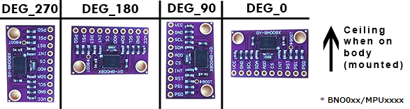
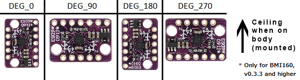
Set Battery Monitoring Options
The following lines define how battery voltage is read:
#define BATTERY_MONITOR BAT_EXTERNAL
#define BATTERY_SHIELD_RESISTANCE 180
If you don't have a 180 kOhm resistor for checking the battery percentage of your tracker, replace BAT_EXTERNAL with BAT_INTERNAL. When set to BAT_INTERNAL the tracker will only be able to tell when the battery is low, and will cause the LED on the microcontroller to flash repeatedly. If you have a 180 kOhm resistor you do not need to change BAT_EXTERNAL. If you have a resistor of value other than 180 kOhm, simply change 180 to whatever your resistor value is in kOhms, for instance 130 if your resistor is 130 kOhms. If you have a Wemos Battery Shield product, you would change 180 to 130 as previously mentioned.
Define Pins of the Selected Board
You need to change only the section between #elif symbols with the selected board. If you are using VSCode, selected board section will light up, while other ones will be grayed out.
Example 1:
#elif BOARD == BOARD_NODEMCU || BOARD == BOARD_WEMOSD1MINI
  #define PIN_IMU_SDA D2
  #define PIN_IMU_SCL D1
  #define PIN_IMU_INT D5
  #define PIN_IMU_INT_2 D6
  #define PIN_BATTERY_LEVEL A0
  #define BATTERY_SHIELD_130K true
Example 2:
#elif BOARD == BOARD_WROOM32
  #define PIN_IMU_SDA 21
  #define PIN_IMU_SCL 22
  #define PIN_IMU_INT 23
  #define PIN_IMU_INT_2 25
  #define PIN_BATTERY_LEVEL 36
  #define BATTERY_SHIELD_130K true
Example 3:
#elif BOARD == BOARD_CUSTOM
  // Define pins by the examples above
  #define PIN_IMU_SDA 5
  #define PIN_IMU_SCL 4
  #define PIN_IMU_INT 14
  #define PIN_IMU_INT_2 13
  #define PIN_BATTERY_LEVEL A0
SDA and SCL pin for main and AUX trackers are always the same. You can define pins either by using pin names, like D1, or by pin number, like 21. Check your board pinout for the details, or connect your tracker to the default pins, they're recommended ones.
You need to put here your selected pins for I2C. Check pinout for details in terms of which ports could be used for I2C.
  #define PIN_IMU_SDA D2
  #define PIN_IMU_SCL D1
If you are using BNO you need to define INT pin:
#define PIN_IMU_INT D5
If you are using the second BNO you need to define INT pin for the second BNO, it must be another pin:
#define PIN_IMU_INT_2 D6
If you are using a resistor for checking the battery level, you will need to select a pin that supports analog input:
#define PIN_BATTERY_LEVEL A0
Your firmware for your MCU and IMU configuration should now be complete!
Created by adigyran with help from Musicman247#1341, edited by nwbx01, edited and styled by calliepepper and emojikage
Building and Uploading the Firmware
Uploading your firmware must initially be done over cable. Once you have the tracker connected to your WiFi after your first firmware update, you can opt to use OTA in the future.
1. Connect Your Tracker to Your PC
If your microcontroller board has a button labeled FLASH, BOOT or RESET, press and hold the button and plug in the micro-USB cable. If you have different labels and/or buttons, please check your microcontroller's manual for more information.
Note that holding the button is not required for Wemos D1 Mini.
2. Build Your Firmware
- Follow the configuring the firmware project page to prepare your project for building and uploading the firmware.
- Press the build button at the bottom of Visual Studio Code.

3. Upload Your Firmware
-
If you are using the OTA method, first make sure the tracker you wish to flash is turned on.
-
Once the firmware has been built, press the upload button to upload the firmware.

-
If the upload is successful, you should get an output that looks like this:
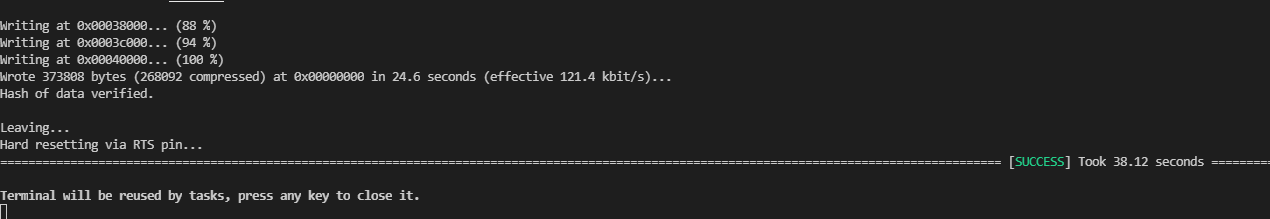
Congratulations! You have now successfully uploaded the firmware to your SlimeVR Tracker!
If you have trouble with uploading your firmware over cable check the following:
- Make sure your USB cable from the tracker is plugged firmly into your PC.
- Make sure that your USB cable is a data and charging cable (it is suggested you try other cables or devices with the cable).
- Make sure that your drivers are up to date.
Additionally, this can be caused by software hogging COM ports (VSCode and Cura can be the cause of this).
Uploading via OTA
Once you have successfully connected your trackers to your WiFi, you can use OTA to handle all future firmware updates.
- Retrieve the IP of the tracker you wish to flash. The IP can be found through network monitoring applications, or by copying it from the SlimeVR Server as seen in the image below:
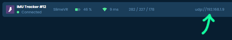
- In
platformio.inifile uncomment the following lines in Visual Studio Code by removing the;:
;upload_protocol = espota
;upload_port = 192.168.1.49
;upload_flags =
;  --auth=SlimeVR-OTA
- Change the value of upload_port to the IP address retrieved during the first step (if retrieved for your SlimeVR server you should only copy the set of 4 numbers between the second and third
/, in the example image above this would be 192.168.1.109). - Turn the tracker you wish to flash off and then on again.
- Wait for the tracker to reconnect to the server.
- Press the upload button to upload the firmware.
- After the upload reaches 100%, wait for the tracker to reconnect to the server again. Turning the device off too soon can result in an incomplete update (bricked until you upload new firmware over USB).
- Repeat for as many trackers as you need.
Troubleshooting
If you encountered an issue while following these steps check the Common issues page.
If you don't find an answer to your question there ask in #diy channel in the discord, we will be happy to help.
Made with care by prohurtz, adigyran, eiren and calliepepper. Edited by calliepepper, emojikage, nwbx01, and nullstalgia.
SlimeVR DIY Kit
Thank you for purchasing the SlimeVR DIY kit!
To get your DIY set operational there are a handful of steps you will need to take. On this page we will guide you through the basic process involved in creating your own ready-to-use set of SlimeVR trackers. While this guide contains some general recommendations, feel free to deviate from the norm and make them truly your own! Have fun!
Introduction
Box contents
SlimeVR DIY 1.2 Kit includes: 8 large SlimeVR Mainboards, 2 small SlimeVR Tracker extensions, and 2 Extension cables (2 short).
SlimeVR DIY 1.0 Kit includes: 7 large SlimeVR Mainboards, 3 small SlimeVR Tracker extensions, and 3 Extension cables (1 long, 2 short).

Required extras
To complete your SlimeVR trackers, you will need some parts in addition to your SlimeVR DIY kit. These include enclosures, straps, batteries, and a USB cable. These are detailed below to make it easier for you to complete your project.
Recommended mounting layout
|
|
|
Designing your case
DIY kits do not come with cases and therefore require enclosures to protect them and allow strap attachment. These can be 3D printed, purchased, or handcrafted. While the official SlimeVR Main and Extension cases are designed to fit the boards included in this kit, they are not optimised for home 3D printers due to their curved surfaces. As such, we recommend printing up your own using a modified design, or designing your own!
The 3D models for the official main and extension cases can be found here. Modified versions of these official cases more suited for home 3D printers, made by tomyum3dp, can be found here.
For those planning to design your own enclosure, you can find the model of the Mainboard here and Extension PCBs here.
Please note, if you are looking for official cases for your official DIY kits those can be found here!.
Using the official case designs?
To complete the assembly you will require 2x M2.5 screws for both the main and extension cases. The modified cases use more the commonly available M3 screws as an alternative. Assembly is as shown below. Included is a video going further in detail on assembly with the official cases!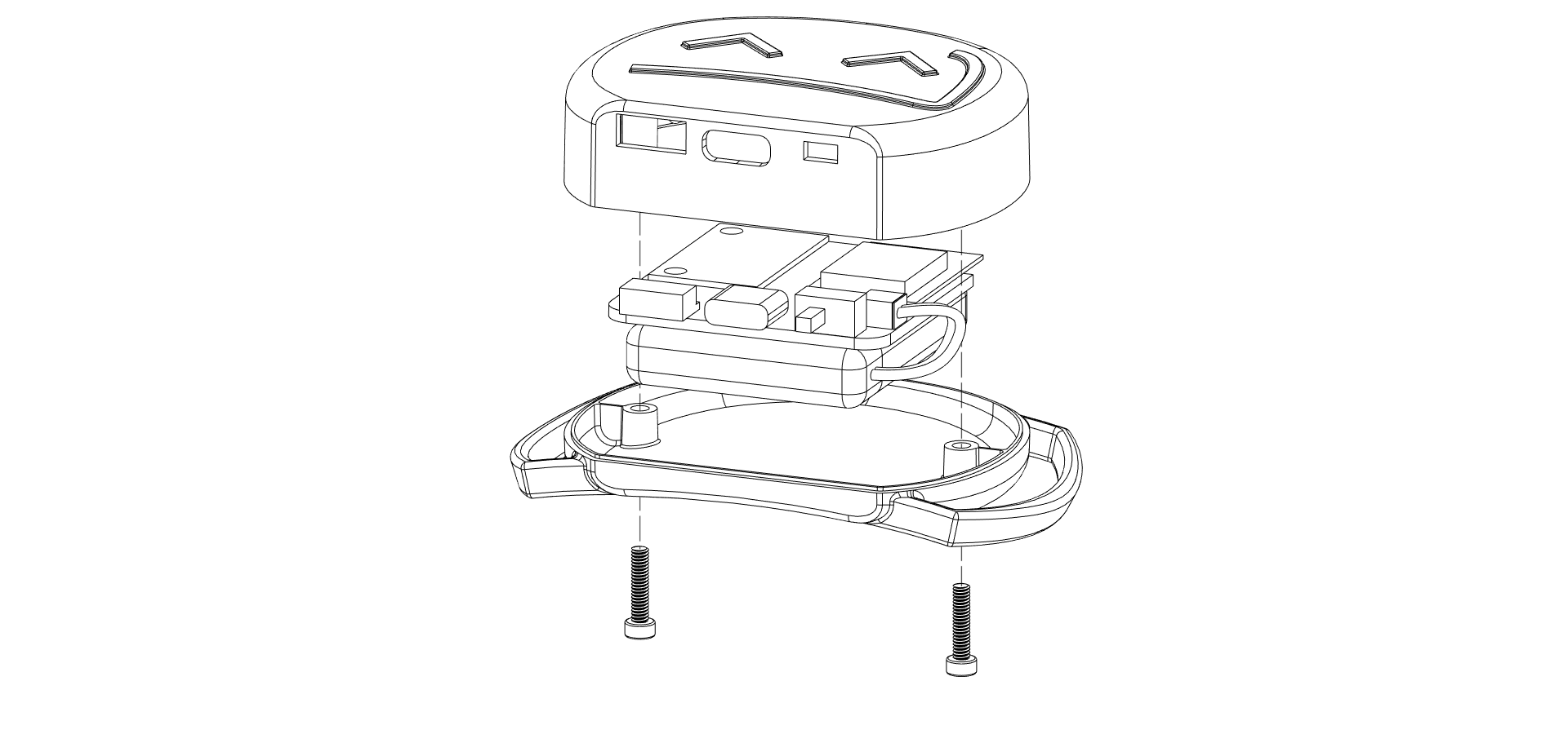
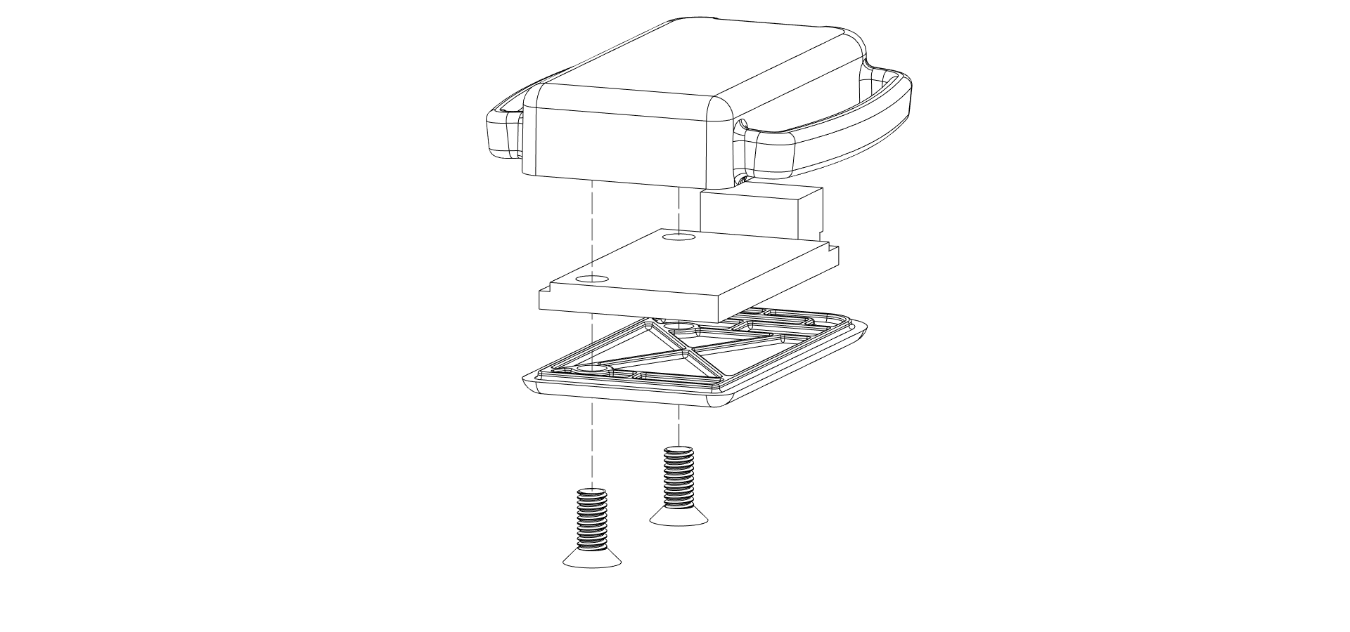
Choosing your battery
The SlimeVR Mainboards included in your DIY kit require power from a battery for the best experience. SlimeVR trackers use approximately 100mAh during use. Extensions do not require their own battery, as they use power from the attached Mainboard. When choosing a battery, select a capacity rating of at least 500mAh to ensure safe use. Charging rate is limited to 500mA to ensure optimal battery lifespan.
We recommend the following specifications:
- Capacity: 1000-1800 mAh
- Nominal Voltage: 3.7v
- Connection: Micro JST-MX 1.25mm
Please note, the integrated charging circuit on the Mainboard is only applicable to lithium based batteries, do not attempt to charge any other battery chemistry types.
The battery dimensions will depend on which case you choose to use or make. Lithium-ion Polymer (LiPo) pouch batteries come in various shapes and sizes, indicated by an XXYYZZ naming scheme that denotes their dimensions in thickness (X.Xmm), width (YYmm), and length (ZZmm). As an example, the official SlimeVR case design uses an 803443 battery, denoting a battery of 8.0mm thickness, 34mm width, and 43mm length.
The mainboards feature a Micro JST-MX 1.25mm male connector port for attaching a battery. As such, it is simplest to choose a battery that has a matching female connector. Alternatively, you can solder or crimp these connectors onto a battery for easy attachment to the Mainboard.
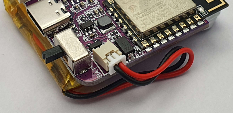
Ensure your battery polarity matches the polarity markings on the PCB, as shown in the example above.
Using the official case designs?
As a guideline, the official and modified cases both feature the following battery cavity dimensions:- 9mm Height (Thickness)
- 41mm Width
- 41mm Length
To use the case without further alterations and ensure safe battery installation, we advise staying within these specifications.
Choosing your straps
You have the option of buying, crafting, and/or customising your straps to your personal preferences. We highly recommend you use elasticised straps with hook and loop fastening, to ensure a comfortable experience and prevent tracker migration.
For tips on making your own straps, check out the DIY Straps Guide.
We recommend the following strap lengths as a baseline guide for choosing your strap design:
- Chest and Hip: 100cm / 40"
- Upper legs (2): 50cm / 20"
- Lower legs (2) and Arms (2): 35cm / 14"
- Feet (2): 30cm / 12"
Note: elastic straps stretch, so you may need less than you think!
The width of the straps you chose is determined by the case you have designed or opted to use.
Using the official case designs?
The official cases use 38mm width straps for main trackers, and 25mm width straps for extensions. The following table of strap sizes used in official SlimeVR sets can be used as a starting reference for purchasing or crafting your own:| Body location | Amount | Strap size (mm) |
|---|---|---|
| Chest strap | 1 | 38x1000 |
| Hip strap | 1 | 25x1000 |
| Upper leg straps | 2 | 38x500 |
| Lower leg straps | 2 | 38x350 |
| Foot straps | 2 | 25x300 |
| Arm straps | 2 | 38x350 |
Optional accessories
SlimeVR DIY Kits Mainboard features a USB Type-C female connector for both recharging and serial connection. As such, at least 1 USB-C cable is required.
We recommend a USB-A to USB-C cable to charge your SlimeVR trackers, and charging using an external USB-A power supply.
Not all cables are built equal, however, most cables will work for charging, as SlimeVR only uses 5 volts at low current. For serial connection, a cable with Data connections is required. If USB serial connection issues arise, ensure your cable features data lines or try a different cable.
Created by vyolex and spazzwan. Photography by eiren. Exploded view renders made by tomyum3dp
Official DIY Clone Trackers
Due to the nature of SlimeVR being open-source it is entirely possible to create your own trackers based on the official design files. Especially now that the SlimeVR Store started selling components such as: cases, cables and IMUs!
- SlimeVR Store
- Where to find the production files
- How to order SlimeVR PCBs from a manufacturer
- Soldering the IMU to the main PCB
- Flashing the firmware
- Final Assembly
SlimeVR Store
Since a little while now there is an official SlimeVR Store! Here you can buy replacement cases, cables and even BNO modules!
Where to find the production files
You can find the production files for both the main tracker, extension boards and the BNO module here: Main Tracker Board, Extension Board and BNO Module. Or the latest revision that doesn't use IMU Modules: Main Tracker R14. These will link you to the respective OSHWLab pages, here you can download the files or directly open them in the online version of EasyEDA.
How to order SlimeVR PCBs from a manufacturer
When you open either of the two links provided above, you will find yourself on the OSHWLab website. From there, you can select "Open in Editor" to access the files in EasyEDA. You do not have to download any software for this process since EasyEDA can run in your browser! Opening the files in EasyEDA allows you to view, edit, or make adjustments if necessary for your specific use case (though this is not required for official clone trackers). Next, navigate to the top bar in EasyEDA, and under "Fabrication," click on "PCB Fabrication file (gerber)." Then, click "no" on both options, as EasyEDA has not been configured yet, and the files are already prepared. From here you can do a one click order. You should be able to leave all the settings as is aside from Surface Finish, set this to LeadFree HASL or ENIG! You can also change the color of the solder mask if you so desire. After this you should be able to continue with the ordering process and then the wait begins!
BEWARE Sometimes when you get redirected to JLCPCB it won't fully load, in this case you might have to try again.
Soldering the IMU to the main PCB
The soldering process for official slimes is a little different than your usual DIY slimes. Where normally DIY slimes are soldered together with through hole wiring, SlimeVR on the other hand uses castelated edges. This makes soldering the IMU very fast and efficient.
What do you need to solder the IMU to the main PCB?
- Soldering iron.
- Leadfree Solder.
- Chisel style soldering tip (optional but recommended).
- Assembly jig (optional).
Instructions:
Place the IMU module on top of the main tracker PCB as shown below.
![]() Now solder the 6 castelated edges to the main board as shown in the picture above.
Using a chisel tip makes this process significantly faster and easier.
For more soldering tips you can check out this video:
Now solder the 6 castelated edges to the main board as shown in the picture above.
Using a chisel tip makes this process significantly faster and easier.
For more soldering tips you can check out this video:
Flashing the firmware
To flash the firmware you will need:
- USB-C cable with data pins (official SlimeVR cable is recommended).
- Paperclip or tweezers to bridge a connection on the PCB.
Flashing the firmware for these official trackers is practically identical to the process of flashing DIY trackers.
A link to the online flasher with all the settings pre-configured can be found here.
If the link does not work or the settings don't show up right after clicking you can find the manual settings a little further down in this section.
As opposed to DIY trackers the official trackers need to be started in flash mode. You can do this by bridging the pads on the top side of the PCB as show below:
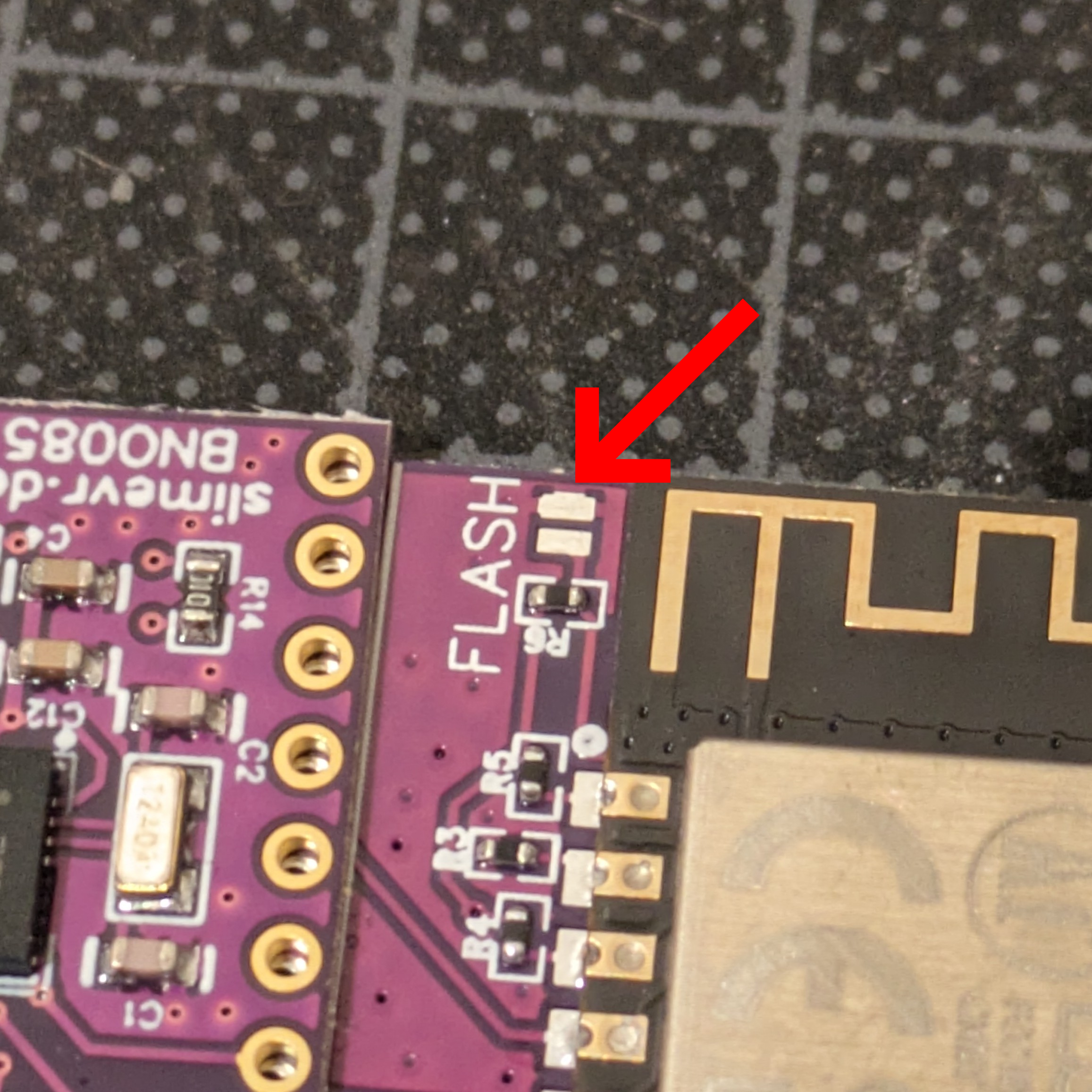 To enter flash mode, turn the tracker's power switch on by switching it to the right, connect the USB cable to the PC, now connect the USB cable to the PCB whilst bridging the exposed flash pads!.
The tracker should now have started in flash mode and be accepting of firmware.
Manual Flashing settings
As stated in defines.h the pins for the official PCB are:- SDA 14
- SCL 12
- INT 16
- INT_2 13
- Battery_Level 17
- LED_PIN 2
- LED_Inverted True
IMU Rotation should be set at 270 for both in case of the official setup using the BNO085.
Final Assembly
For final assembly we would like to refer to the official SlimeVR repair guide. This contains information regarding both assembly and disassembly. On an additional note, the sticky foam pad usually sits on the printed side of the battery (in the case of production units).
Written Assembly Guide
| Amount | Part |
|---|---|
| 1x | Case Top |
| 1x | Case Bottom |
| 2x | M2.5x10 Screw or M2.5x12 |
| 1x | PCB |
| 1x | Battery |
| 1x | Foam Pad |
| 1x | Sticker |
Attach a foam pad to the center of the battery (text side). Attach battery cable to the PCB. Turn on the tracker by sliding the switch to the right, make sure the blue light blinks continuously. Turn off the tracker by sliding the switch to the left! Place the PCB with the components facing down into the top case(make sure to insert at an angle, the ports are aligned and it sits flush). Place the battery with the foam side against the PCB, making sure the cable gets tucked under the battery. Place the bottom case halve on the assembled top halve. Screw the m3 screws into the cases to securely close it up, be careful not to pinch the battery cable! Place the sticker on the back.
Created by Smeltie
Disclaimer: This project is highly experimental. These devices may be incompatible with older versions of the SlimeVR Server and could require frequent firmware updates. Nothing is final at this stage, including hardware, firmware, and communication protocols.
Smol (nRF-Based) vs Normal ESP (WiFi-Based) SlimeVR Trackers
Currently, Official SlimeVR trackers and most DIY trackers connect to the SlimeVR Server via a 2.4 Ghz WiFi network. Smol Trackers change this by communicating wirelessly with a dongle plugged into the user’s computer/headset/phone, removing the need for an available WiFi network.
Quick Comparison
| Tracker Type | Communication Method | Average Weight | Battery Life | Range | Summary |
|---|---|---|---|---|---|
| Official WiFi Trackers | 2.4 Ghz WiFi | 50 g | 18-20 h | WiFi coverage | Much greater range. Trackers are bulkier and have lower battery life. Requires WiFi setup and is dependent on network conditions. |
| Smol/Butterfly Trackers | Enhanced ShockBurst (ESB) | ~10-15 g | 40-60 h | 7-12m from receiver (21-36 ft) | Lower range. Trackers have much greater battery life and are smaller. Trackers must be paired to a dongle connected to host device. |
So what are the actual differences?
1. Protocol
Typical WiFi-based Trackers communicate via WiFi directly with the SlimeVR Server. Smol Trackers instead use a heavily modified fork of the Enhanced ShockBurst (ESB) protocol on an nRF52 or nRF54 microcontroller to communicate with the host device via a receiver; allowing for lower latency and lower power draw at the cost of range.
2. Size and Battery Life
Current Official Trackers utilize a 1350 mAh battery, lasting on average from twelve to eighteen hours of use.
The recommended Smol Tracker design uses a 401230 110 mAh battery, targeting a minimum battery life of 24 hours; though it often exceeds 40 hours in recommended configurations.
Smol Trackers have the additional benefit of a much smaller PCB, leading to an average weight between 10 to 15 grams depending on the design. Official Trackers are larger and heavier, weighing around 50 grams.
An Official Tracker (left) and Ibis 2.0 Smol Tracker (right)
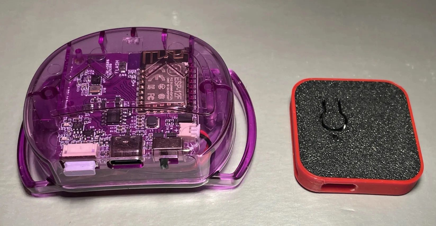
Image by Zrock35. Note that the Ibis 2.0 Tracker pictured is roughly 3 cm by 3 cm and weighs 10 grams.
3. DIY differences
This is explained in greater detail in the respective DIY guides for WiFi-based and nRF-based trackers.
- WiFi-based trackers currently require a carrier PCB, an IMU board, and a charging board, alongside a battery.
- A typical Stacked Smol set consists of five or more trackers connected to one or more receivers.
- Trackers based on nRF52840 boards, with one IMU and battery per board
- Receivers, aka dongles, are required to connect trackers to the server. These are also typically based on nRF52840 or nRF54L boards.
- For more information, see the official Smol documentation
4. Standalone Compatible?
Yes, Smol Trackers are compatible with standalone VRChat. An OTG adapter is required if the device running SlimeVR does not have a USB-A port.
The Open Sound Control (OSC) protocol must be configured in SlimeVR to send tracking data from the server over WiFi to standalone VRChat.
I heard Butterfly. What's that?
🦋 Introducing the Butterfly Tracker – SlimeVR's Official Smol Tracker
Looking for something simpler than building your own? The Butterfly Tracker will be SlimeVR’s official take on the Smol Tracker—ultra-thin, lightweight, and ready to use out of the box.
🔗 Learn more and view the campaign on CrowdSupply.
Created by Shine Bright ✨, Amebun, Depact and Seneral
Smol Hardware
This section provides an overview of the hardware used in Smol Slimes trackers and receivers, serving as an entry point to more detailed guides.
What You'll Find in this Section
-
Receiver Overview of receiver hardware, USB dongle options, antenna modifications, and signal strength tips.
-
Tracker Detailed guide on tracker hardware, including microcontroller boards, IMUs, magnetometers, batteries, buttons, switches, and assembly tips and schematics.
-
DIY Set Cost Calculator An interactive tool to help you estimate the cost of building your own Smol tracker set.
Created by Shine Bright ✨ and Depact
Smol Receiver
Table Of Contents
- 📶 Receiver Options (Ranked by Signal Strength)
- 📡 USB Dongles
- 📡 Microcontrollers Modified Into USB Dongles
📶 Receiver Options (Ranked by Signal Strength)
To ensure optimal signal integrity and range, it is essential to use boards equipped with high-quality antennas. Boards featuring a PCB antenna or external antenna are generally the most effective option for use as receivers.
Nordic Semiconductor nRF52840 Dongle, Seeed Studio XIAO nRF52840 are not included due to lack of data.
| Receiver | Tier | Typical Price (USD) | Notes / Best For |
|---|---|---|---|
| 🟢 HolyIOT-21017 | Superior | ~8-18 USD |
Highest performance for the highest price.
Includes an RFX2401C FEM amplifier — reported to provide significantly increased signal strength. |
| 🟠 ProMicro nRF52840 with Wi‑Fi Antenna Mod | Affordable | ~7 USD | Best price‑to‑performance when modified with a Wi‑Fi antenna. |
| 🟠 ProMicro nRF52840 with Wire Antenna Mod | Affordable | ~6 USD | Simple 31.2 mm wire monopole antenna; low cost and easy to build; modest range improvement. |
| 🟠 eByte Dongle (E104-BT5040U) | Limited | ~6,25 USD for min pack of 2 on Alibaba | Cheapest PCB‑antenna dongle. Signal tends to degrade beyond ~3 m, especially when obstructed by body parts. |
| 🚫 ProMicro nRF52840 (Unmodified) | Avoid | ~2-4 USD | Unmodified board; Same as trackers. Not recommended, as antenna mods are better. |
📡 USB Dongles
These dongles are equipped with relatively well-optimized PCB antennas. For improved signal integrity, especially in constrained environments, consider using a USB extension cable.
| Dongle | Description | Links |
|---|---|---|
| 🟠 eByte Dongle (E104-BT5040U) |
Cheapest option with a PCB antenna. - E104-BT5040U is the correct model to use. It is fully compatible with the Nordic Semiconductor nRF52840 Dongle. - E104-BT5040UA is not compatible. It is only capable of capturing BLE4.2 and BLE5.0 protocol packets. |
|
| Nordic Semiconductor nRF52840 Dongle (PCA10059) | Official Nordic development hardware. | |
| 🟢 HolyIOT-21017 aka HOLYIOT-21017-nRF52840 | Has a FEM (Front End Module), specifically an RFX2401C radio booster. Currently regarded as the highest-performance option. |
📡 Microcontrollers Modified Into USB Dongles
🚫 Option 1: Unmodified Board
Consist of ProMicro nRF52840 or Seeed Studio XIAO nRF52840.
🟠 Option 2: Wire Antenna Mod
Consist of a ProMicro nRF52840 or Seeed Studio XIAO nRF52840 attached with a 31.2 mm wire to the antenna pin to form a basic monopole antenna.
Refer to Smol Schematics -> Antenna (extra option) for the solder point location.
Wire Options
- Solid core or stranded copper wire (e.g., 23-26 AWG).
- Wire salvaged from an Ethernet cable.
🟠 Option 3: Wi-Fi Antenna Mod
Consist of a ProMicro nRF52840 or Seeed Studio XIAO nRF52840 attached with a Wi-Fi antenna.
Recommended due to a good balance between build difficulty, performance, and cost.
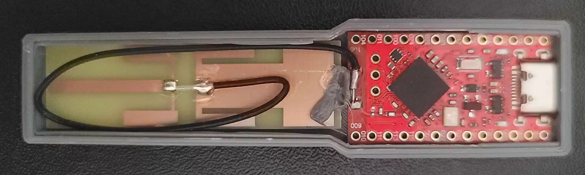 Example receiver from LyallUlric's Stacked SmolSlime build, equipped with an OOTDTY 2.4G/5.8G Dual Band Antenna.
Refer to Smol Schematics -> Antenna (extra option) for the area to remove and solder the IPEX or SMA connector.
Community-Tested Antennas
Community Recommendation
| Image | Listing | Link |
|---|---|---|
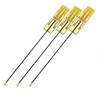
|
OOTDTY 5 Pcs 2.4G/5.8G Dual Band Antenna 8DBI High Gain Internal PCB Aerial for WiFi Router WiFi Antenna |
IPX–SMA Conversion Setup
| Image | Listing | Notes | Variant | Link |
|---|---|---|---|---|
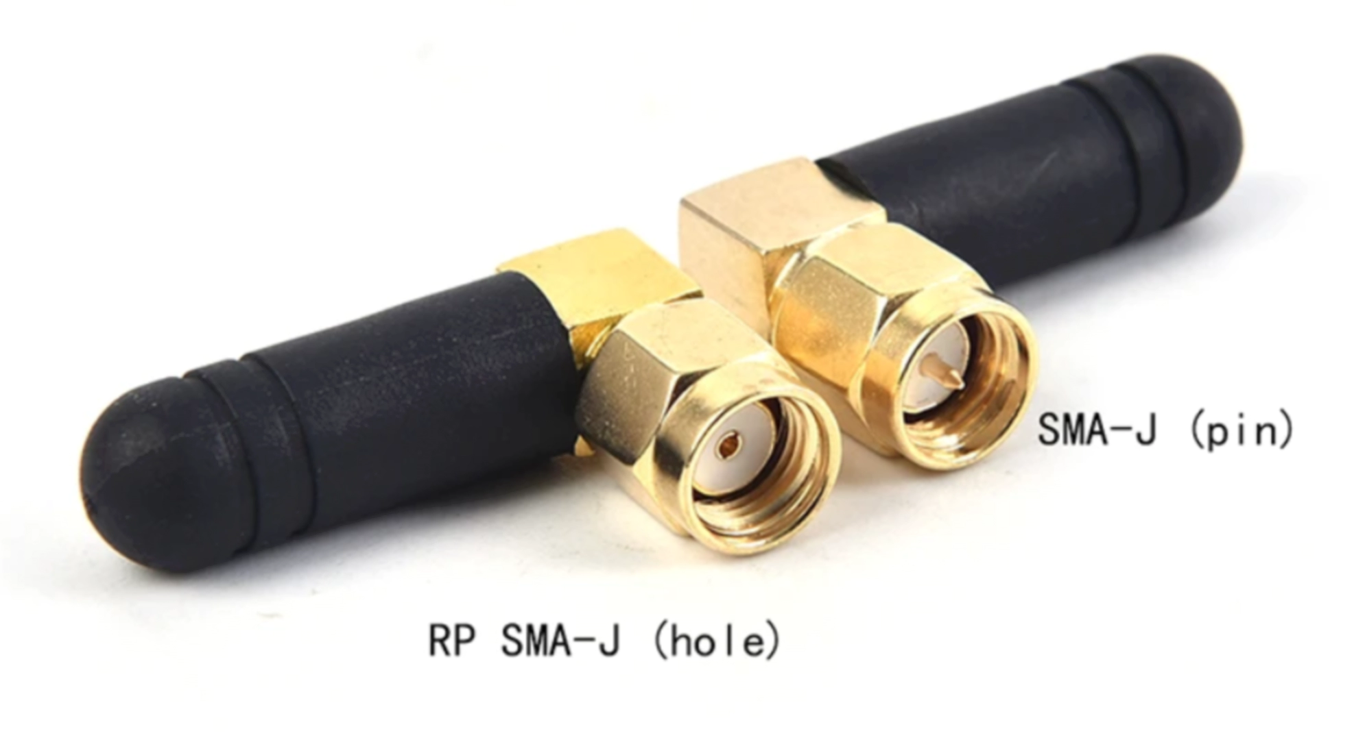
|
2PCS Mini Rubber 3dBi 2.4ghz WIFI Antenna SMA Male Router Bluetooth Antennas Wireless Module 2.4g Antena External Aerial | Best tested performance (based on Lyall’s tests) | Color: B | |

|
IPX to SMA RF Coax Adapter Assembly Pigtail Cable,SMA Connector Cable Female to UFL |
Any IPEX or SMA cable should do.
Cut cable at marked location on the image. |
Shorter cables preferred. |
Created by Shine Bright ✨, Depact and Seneral
🏃 Smol Tracker
Before you start, decide on how many trackers you may need.
Trackers are required to have a battery and an inertial measurement unit (IMU). A magnetometer is optional.
Buttons and slide switches are recommended but not required. Buttons can be added to control the tracker, and a slide switch can be used to physically disconnect a tracker's battery.
Table Of Contents
Schematics
Tracker Parts
📻 Microcontroller Boards
| Board | Description | Obtaining |
|---|---|---|
| ProMicro nRF52840 |
A clone of the nice!nano board. Cheapest option
overall. Signal strength can be improved with antenna mod. |
Available on AliExpress with
compatible with nice!nano, SuperMini, or
Pro Micro branding.
|
| Seeed Studio XIAO nRF52840 | Compact board. |
🧭 Inertial Measurement Units
Some of the supported sensor modules are described on the IMU Comparison page.
- BMI270
- ICM-42688-P
- ICM-42688-V
- ICM-45686
- ISM330BX
- ISM330DHCX
- ISM330DLC
- LSM6DSL
- LSM6DSM
- LSM6DSO
- LSM6DSR
- LSM6DSV
- LSM6DSV16B
🧲 Magnetometers
- AK09940
- BMM150 Sensor driver has not been tested.
- BMM350 Sensor driver has not been tested.
- IIS2MDC
- IST8306
- IST8308
- LIS2MDL
- LIS3MDL Sensor driver has not been tested.
- MMC5983MA
- QMC6309
🟩 Sensor Modules with IMU and Magnetometer
IMU + Magnetometer Modules
| IMU + Magnetometer | Product Page |
|---|---|
| ICM-45686 + QMC6309 | shop.slimevr.dev |
| LSM6DSV + QMC6309 | moffshop.deyta.de |
| Chrysalis LSM6DSV + QMC6309 | nekumori.pink |
🖲️ Buttons
Push buttons and momentary switches are utilized to control the tracker. The functions of this button—Reset, Calibration, Pairing, Deep Sleep, and entering DFU Mode—depends on the number of press combinations. A tracker can be equipped with either a reset button, a user-specified (SW0) button, or both.
The reset button is designed to support all functionalities. If an user-specified button (SW0) is defined, it will be utilized instead.
If a button is unavailable, tweezers can be used to short the pins for the initial tracker setup.
🕹️ Switches
A slide switch can be used to physically disconnect a battery. Some boards have a high standby power draw and will require a switch.
If a switch is not utilized, a tracker can enter Deep Sleep mode by pressing and holding down the user-specified button (SW0).
🔋 Batteries
Safe battery charging rates (C) are correlated to their rated capacity (mAh). A 100mAh battery charging at 100mA is 1C, and a 200mAh battery charging at 100mA is 0.5C. Charging at lower rates near 0.5C is recommended to reduce battery stress and extend lifespan.
| Board | Default charge rate | Minimum battery capacity | Recommended battery capacity |
|---|---|---|---|
| Seeed Studio XIAO nRF52840 | 50mA | 50mAh | 80-300mAh |
| ProMicro nRF52840 | 100mA | 100mAh | 180-300mAh |
📶 Copper Wire for Wire Antenna Mod
Cheap and easy way to improve signal strength.
Consists of 31.2 mm wire attached to the antenna pin to form a basic monopole antenna. Longer is fine too.
Refer to Smol Schematics -> Antenna (extra option) for the solder point location.
Notes:
- Has to be isolated to avoid a short circuit on other components.
- Branded wire slightly worse than solid core, but not significantly.
- Wire can be sourced from ethernet cable.
📏 Kapton Tape (Stacked Only)
It is placed between the board and the IMU, on the back of the IMU, to prevent shorts and protect components.
🧤 Strap
Tracker require straps or mounting solutions for practical use.
Community-designed strap solutions can be found on the
Smol Community Straps page.
📦 Case
Case protect components, improve durability, and make trackers easier to mount or wear.
Community-designed cases can be found on the
Smol Community Builds page.
Created by Shine Bright ✨, Depact, Aed, and Seneral with images from Meia and Firmata
Smol DIY Set Cost Calculator
Default selected values are chosen to offer the best price-to-performance balance.
For better performance, change the selection to the following value:
- IMU: ICM-45686
Select Number of Trackers
Before you start, decide on how many trackers you may need.
Select Parts
| Component | Choice | Amount | Cost per one | Cost with Shipping | Quick Link |
|---|
Breakdown
- One dongle support 10 trackers, but 8 trackers per receiver recommended.
- 401230 3.7V 110 mAh Battery generally provides 40-60 hours of battery life, depending on use and components use.
Steps After Acquiring Parts
Once gathered parts those steps remain to build fully functional set:
Created by Shine Bright ✨ and Depact
Smol Community DIY
Explore community-created builds, straps, and docks to help you assemble or customize your own Smol trackers.
What you'll find in this section
-
Community Builds Showcases community-submitted Smol tracker builds, including photos and build notes.
Only builds with sufficient detail to be reproducible are included. -
Community Straps Community-sourced designs and guides for creating comfortable and secure straps for Smol trackers.
-
Community Docks Community-sourced designs and guides for docks compatible with Smol trackers.
Created by Shine Bright ✨ and Depact
Smol Community Builds
This page is dedicated to builds that anyone can reproduce.
Builds that are not open-source or lack sufficient documentation to be replicated are not listed here.
Table Of Contents
- Stacked Community Builds
- Non Stacked Community Builds
- 🚫 Not Recommended For New Tracker Builds
- Contribution
Stacked Community Builds
In stacked designs IMU sits on top of board. This allows easy swap of cases, if battery also fit.
| Image | Name | Author | Link | USB | Battery | Strap Width | Dock | Dongle |
|---|---|---|---|---|---|---|---|---|
|
|
Gremlin | ManicQuinn | GitHub | ✅ |
110 mAh
401230 Battery
|
30 mm | ✖️ | ✖️ |

|
Smol Panini Case | TigsterCox | Github | ✅ |
180 mAh
601230 Battery
|
30 mm | ✖️ | ✖️ |
|
|
Ibis Trackers | brisfknibis | Github - Stacked | ✅ |
120 mAh
401230 Battery
|
30 mm | ✅ | ✖️ |

|
Stacked SmolSlime | LyallUlric | Thingiverse | ✅ |
100 mAh
401030 Battery
|
30 mm | ✖️ | ✅ |
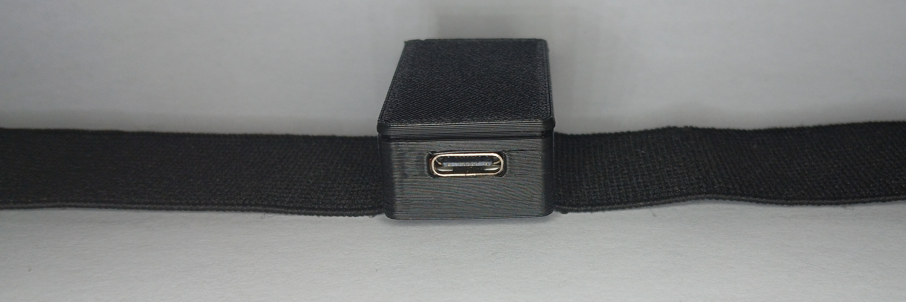
|
SmolSlimeSMOL | ICantMakeThings | Thingiverse | ✅ |
500 mAh
402035 Battery
|
25mm | ✖️ | ✖️ |
|
|
Miro Trackers | spiro.ooo | Github | ✅ |
120 mAh
401230 Battery
|
25mm/38mm | ✖️ | ✖️ |
Non Stacked Community Builds
Ibis Chrysalis listed as non stacked, as it require "Chrysalis" shield. It makes it incompatible with other stacked cases, and it's cases are incompatible with stacked designs, that not use this shield.
| Image | Name | Author | Link | USB | Battery | Strap Width | Dock | Dongle |
|---|---|---|---|---|---|---|---|---|

|
Aed-Slimes | Aed | GitHub | ✅ |
120 mAh
LIR2450 Battery
|
35 mm | ✖️ | ✖️ |
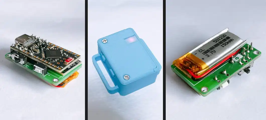
|
Marzipan | Colanns | GitHub | ✅ |
110 mAh
401230 Battery
/
170 mAh
501230 Battery
|
25 mm | ✖️ | ✖️ |
|
|
Ibis Trackers | brisfknibis | Github - Chrysalis | ✅ |
120 mAh
401230 Battery
|
30 mm | ✅ | ✖️ |
🚫 Not Recommended For New Tracker Builds
| Image | Name | Reason Not Recommended | Author | Link | USB | Battery | Strap Width | Dock | Dongle |
|---|---|---|---|---|---|---|---|---|---|
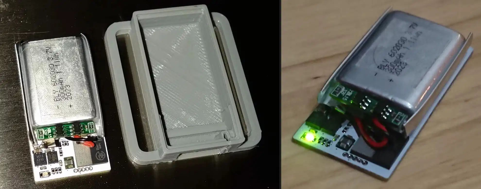
|
SlimeNRF R1/R2 | I2C only design | sctanf | GitHub | ✖️ |
300 mAh
601230 Battery
|
35 mm | ✅ | ✖️ |
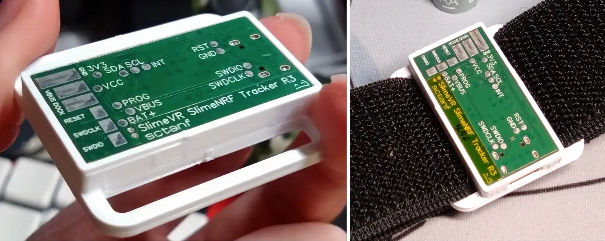
|
SlimeNRF R3 | I2C only design | sctanf | Oshwlab | ✅ |
80 mAh
301230 Battery
/
100 mAh
242030 Battery
|
35 mm |
✅
Use SlimeNRF R1/R2 dock.
|
✖️ |
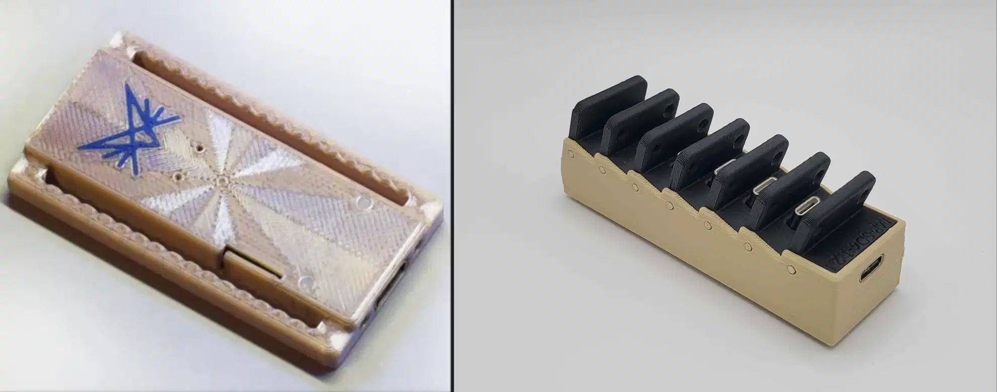
|
SlimeNRF-Fuimini | I2C only design | Zipra1 | GitHub | ✅ | 100 mAh | 50 mm | ✅ |
✅
Custom case for eByte E104-BT5040U Dongle.
|
Contribution
Want to contribute your design? Awesome! To have your build added to this list, please ensure the following:
- Your case must be publicly accessible (e.g. GitHub (preferable), Thingiverse, etc).
- Include at least one clear image or render of your build with a 2:1 or 3:1 aspect ratio.
- Provide basic build information:
- Does it have a USB port?
- What battery size/type does it use?
- Is it compatible with a dock? / Does it include a dock?
- Submit your case by opening a pull request.
Created by Shine Bright ✨ and Depact
Smol Community Straps
Welcome to the Smol Community Straps page!
Here you'll find a curated collection of DIY strap solutions contributed by the SlimeVR community.
Table of Contents
Common Components
For information on common strap components, 3D printable buckles, and tracker placement, refer to DIY Straps Components
Community Strap Builds
Depact Smol Strap V3
Design by Depact
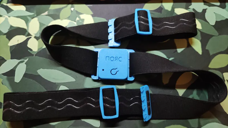
Summary
V3 extends V2 and significantly reduces sliding during activities like dancing and movement.
👍 Pros:
- No sewing needed
- Modular: any part can be replaced
- Minimal tools needed: just scissors
👎 Cons:
- 3D printing is required
Notes
- Make straps one by one to determine the correct length.
- The dovetail design was chosen based on buckle rankings at the time and can be replaced if desired.
- Raw edges can be sealed with heat to reduce fraying. The linked band material has been tested for edge sealing with heat. Use caution if melting edges, and avoid creating a fire hazard.
Assembly Steps
- Wrap the band snug, not tight around each spot of tracker placement.
Keep the band flat and level.
Add 10 cm to each measurement. You can always cut down, but you need to leave enough to be able to adjust. - Cut band.
- Put the case, slides and buckles on the band.
Required Components
| Component | Usual Listing Name | Color/Variant | Link |
|---|---|---|---|
| GoPro Chest Strap | Chest Strap Mount | Black | AliExpress |
| 5m of 30mm Elastic Band with Non-slip Silicone Webbing | Elastic Band Non-slip Webbing | EB312-Black-30mm, 5Meters | AliExpress |
| 3D Printed Buckle | Dovetail Strap Latch 30mm | Documentation | |
| 3d Printed Slide | 30mm, Slide Buckle by Guidoo | Documentation |
Previous Depact Smol Strap versions
Click to show
Previous Depact Smol Strap Versions
🚫 Depact Smol Strap V2
Design by Depact
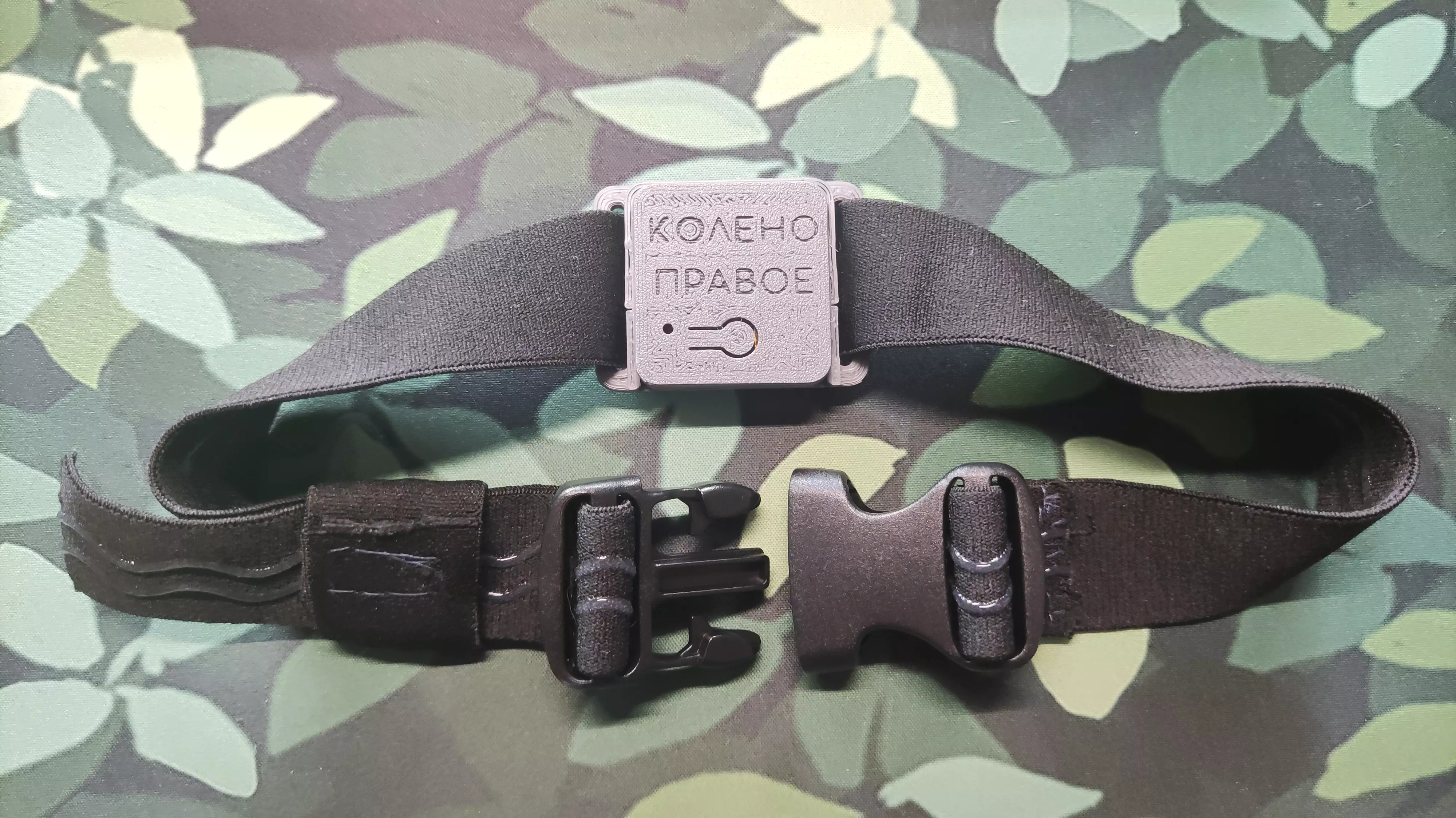
Summary
Same bare-bones and modular approach as V1, but it also requires a needle and thread. It’s recommended to replace the buckle with a good 3D printed one.
👍 Pros:
- So bare-bones that any part can be replaced if needed.
- Minimal tools needed: just scissors and a needle.
👎 Cons:
- May not be as convenient as straps with hook-and-loop fasteners.
Assembly Steps
- Wrap band around tracker position.
- Cut band slightly longer than needed to wrap around.
- Put the case and the buckles on the band.
- Sew one end of the buckle to the band.
- Now, make the loop keeper.
- Cut one piece of band per strap, slightly shorter than three times the strap’s width, so the loop sits snugly when sewn.
- Wrap this piece snugly around the strap to secure both the strap and the loose tail extending from the unsewn buckle.
- Sew the loop keeper, being careful not to sew it to the strap.
Additional links
Required Components
5 meters of elastic band are generally enough to make 6 straps for an average man wearing European size XL.
| Component | Listing Name | Color/Variant | Link |
|---|---|---|---|
| Belt Buckles with webbing size 32mm, 10pcs pack | 20mm 25mm 32mm~50mm Plastic Hardware Dual Adjustable Side Release Buckles Molle Tatical Backpack Belt Bag Parts Strap Webbing | Webbing Size 32mm, 10pcs | AliExpress |
| 5m of 30mm Elastic Band with Non-slip Silicone Webbing | Meetee 2/5/10Meters Elastic Band 20-50mm Non-slip Webbing For Belt Garment Wave Silicone Ribbon DIY Clothes Sewing Accessories | EB312-Black-30mm, 5Meters | AliExpress |
| GoPro Chest Strap | Chest Strap Mount Belt for Gopro Hero 9 8 7 6 5 4 Insta360 R X2 DJI OSMO Action Camera Harness for Go Pro SJCAM EKEN Accessories | Black | AliExpress |
| Needle and thread | Common in DIY and specialized shops |
🚫 Depact Smol Strap V1
Design by Depact
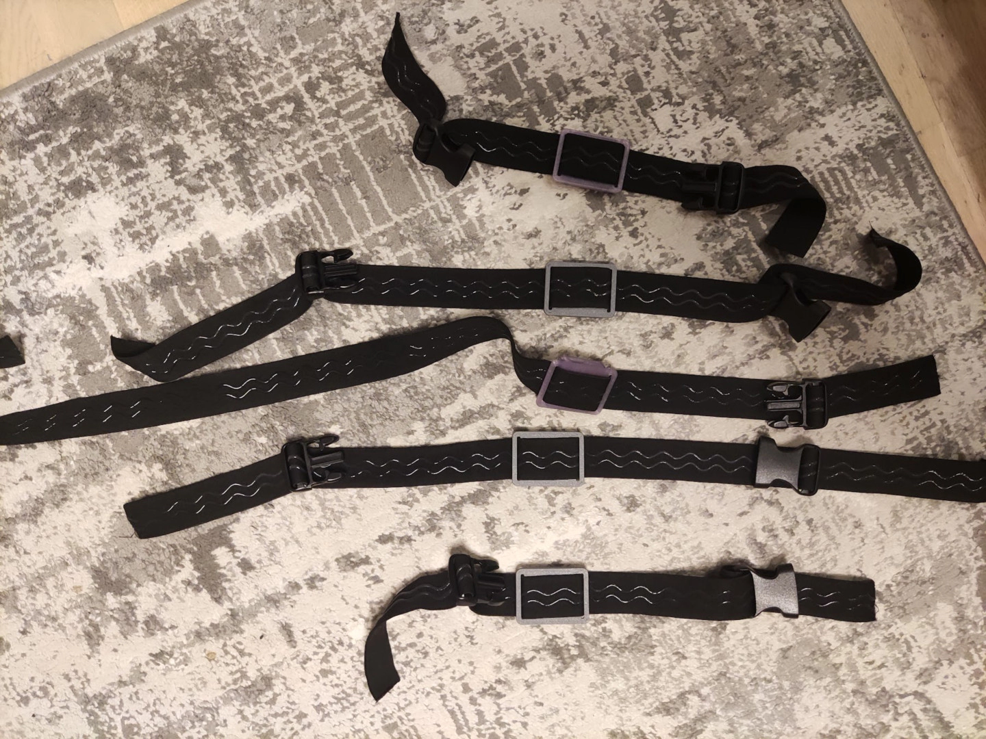
Summary
This setup is extremely minimal. It's recommended to replace the buckle with a good 3D printed one.
👍 Pros:
- So bare-bones that any part can be replaced if needed.
- No sewing required.
- The only tool needed is scissors.
👎 Cons:
- Straps may slide within the buckle.
- Attachment may be less secure.
- May not be as convenient as straps with hook and loop fasteners.
Assembly Steps
- Wrap band around tracker position.
- Cut the band slightly longer than needed to wrap fully around the placement.
- Attach the case and buckles to the band.
Required Components
5 meters of elastic band are generally enough to make 6 straps for an average man wearing European size XL.
| Component | Listing Name | Color/Variant | Link |
|---|---|---|---|
| Belt Buckles with webbing size 32mm, 10pcs pack | 20mm 25mm 32mm~50mm Plastic Hardware Dual Adjustable Side Release Buckles Molle Tatical Backpack Belt Bag Parts Strap Webbing | Webbing Size 32mm, 10pcs | AliExpress |
| 5m of 30mm Elastic Band with Non-slip Silicone Webbing | Meetee 2/5/10Meters Elastic Band 20-50mm Non-slip Webbing For Belt Garment Wave Silicone Ribbon DIY Clothes Sewing Accessories | EB312-Black-30mm, 5Meters | AliExpress |
| GoPro Chest Strap | Chest Strap Mount Belt for Gopro Hero 9 8 7 6 5 4 Insta360 R X2 DJI OSMO Action Camera Harness for Go Pro SJCAM EKEN Accessories | Black | AliExpress |
Contributing
Want to share your own DIY strap design, tip, or resource?
We welcome community contributions!
- How to contribute:
- Suggest changes, share your ideas and experience in the SlimeVR Discord -> Suggestions on strap improvements channel.
- Or, open a pull request on the SlimeVR Docs GitHub repository.
When contributing, please include clear photos, a description, and any relevant links or files. Your contribution helps make VR more accessible and easier to build for everyone!
Created by Shine Bright ✨ and Depact
Smol Community Docks
Welcome to the Smol Community Docks page! Here you'll find a curated collection of DIY dock solutions contributed by the SlimeVR community.
Table Of Contents
Community Dock Builds
Depact Smol Sudo Dock
An extremely minimal dock setup using a USB hub and OTG connectors.
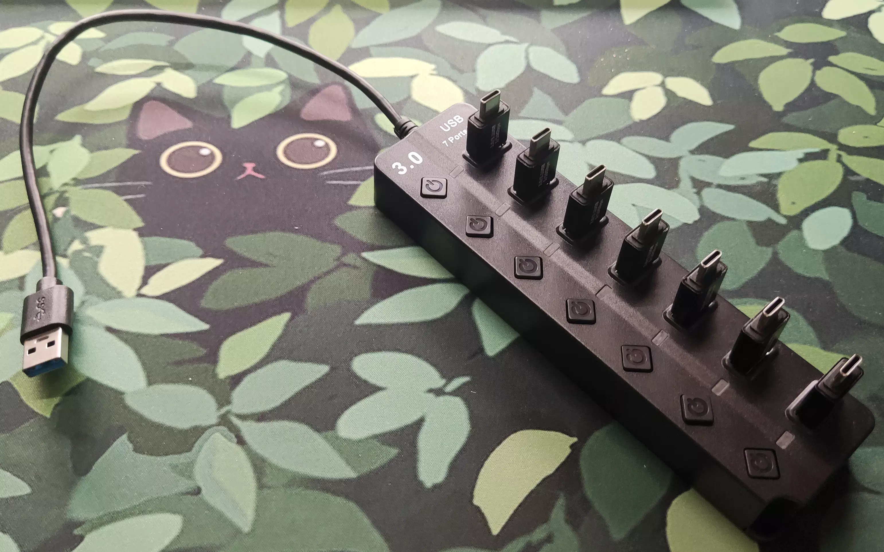
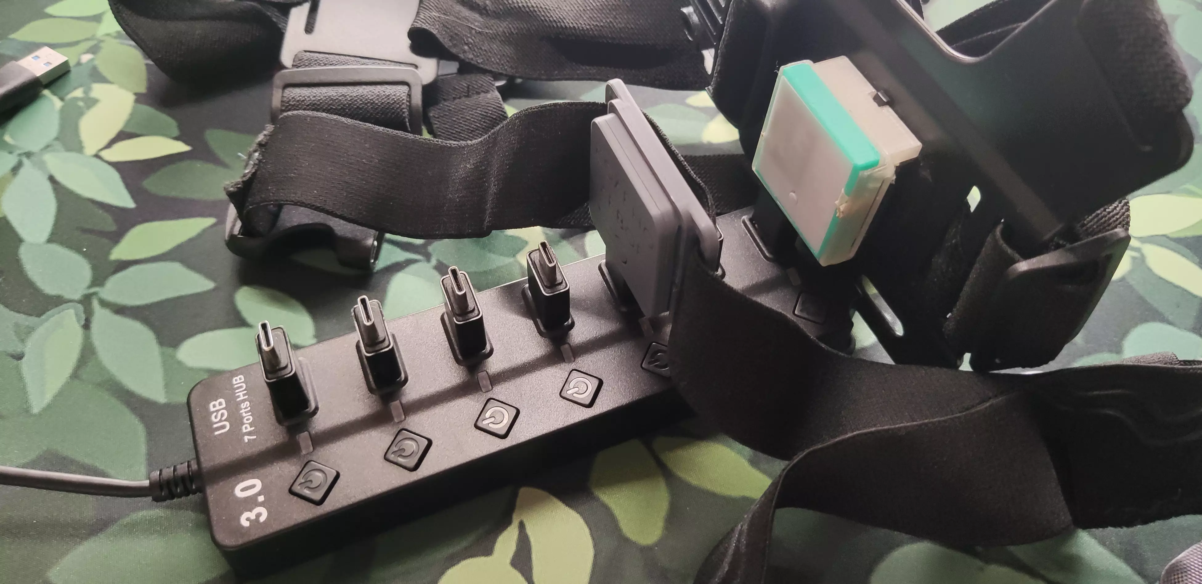
Parts
| Part Description | Link | Notes |
|---|---|---|
| 7-Port USB 3.0 Hub | AliExpress | Any USB 3.0 hub with sufficient ports should work |
| Type-C Male to USB-A Male OTG Connector | AliExpress | Can be replaced with short USB-A to USB-C cables |
Assembly
Assembly is as simple as inserting the OTG connectors into the hub.
Pros and Cons
Pros:
- Extremely affordable and very easy to assemble
- Flexible, with readily available parts
- Allows storing trackers without removing straps
Cons:
- OTG connectors may loosen or fall out
- Overall structure can feel flimsy
Contributing
Want to share your own DIY dock design, tip, or resource? We welcome community contributions!
- How to contribute:
- Suggest changes and share your ideas in the SlimeVR Discord
- Or open a pull request on the SlimeVR Docs GitHub repository
When contributing, please include clear photos, a description, and any relevant links or files. Your contribution helps make VR more accessible and easier to build for everyone!
Created by Shine Bright ✨ and Depact
Smol Tracker Soldering
This page offers two ways to learn to solder your Smol Tracker: a video tutorial and a step-by-step text guide. Choose the method that works best for you!
Table of Contents
Lyall's Soldering Video Tutorial
If you prefer to watch a demonstration, you can follow along with the video below.
Depact's Soldering Text Tutorial
Tools Needed
Essential Tools
- Side cutter pliers
- Tweezers (used for holding buttons and header pins in place)
- Soldering iron
- Soldering sponge (used for cleaning the soldering iron tip)
- Flux-cored solder wire (recommended for ease of use over separate solder and flux)
- Scissors (used for cutting Kapton tape)
Optional Additional Tools
- Soldering jig (optional, but makes holding the board easier)
- Soldering mat (optional, protects your workspace)
Types of PCB Soldering Defects and Solutions
Visual guide for PCB soldering and identifying soldering defects and proper solder joints.
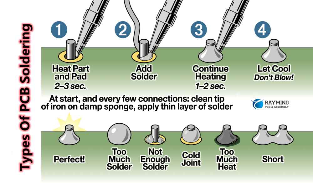
Image source: [RayPCB](https://www.raypcb.com/pcb-soldering/)
Soldering Steps
-
Solder the Button
- Prefill the through-holes under the button contacts with solder.
- Place the button onto the solder-filled holes.
- Heat the area with the soldering iron until the solder connects the button pads securely.

-
Solder the Breakaway Header
- Break off a segment of 6 pins from the breakaway header strip.
- Insert the header into the through-holes, leaning it slightly toward the center of the board to hold it in place.
- Solder each pin one by one, making sure they remain straight and securely attached.
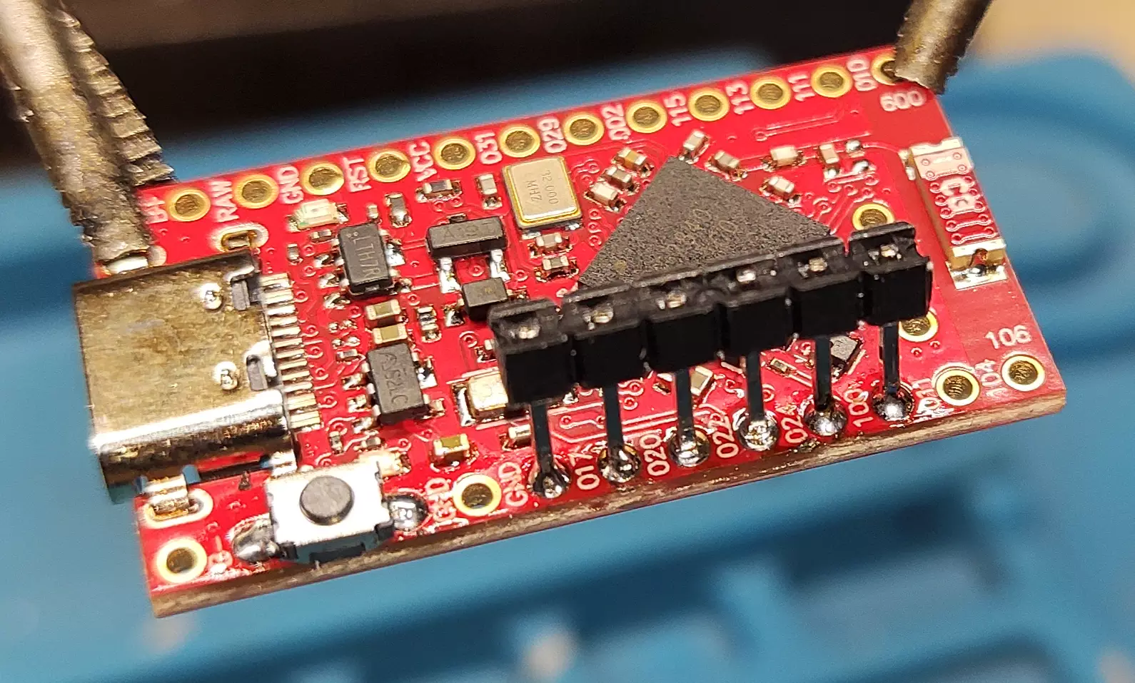
-
Insulate the IMU
- Cover the back of the IMU module with Kapton tape to prevent shorts.
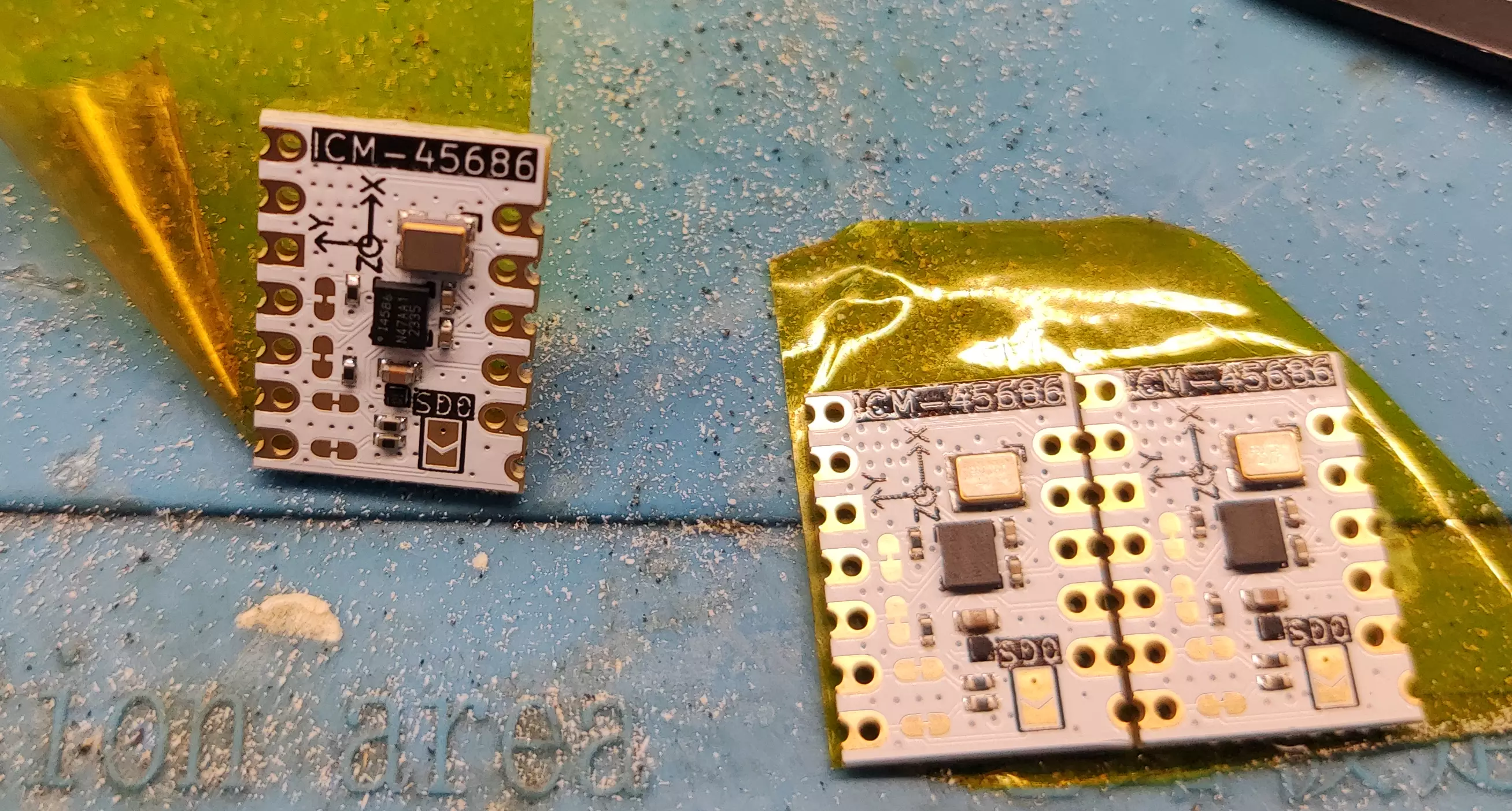
- Cover the back of the IMU module with Kapton tape to prevent shorts.
-
Solder Headers to the IMU
This tutorial shows how to solder the ICM-45686. For other IMUs, see Smol Tracker Schematics.
- Solder a row of breakaway headers to one side of the IMU.
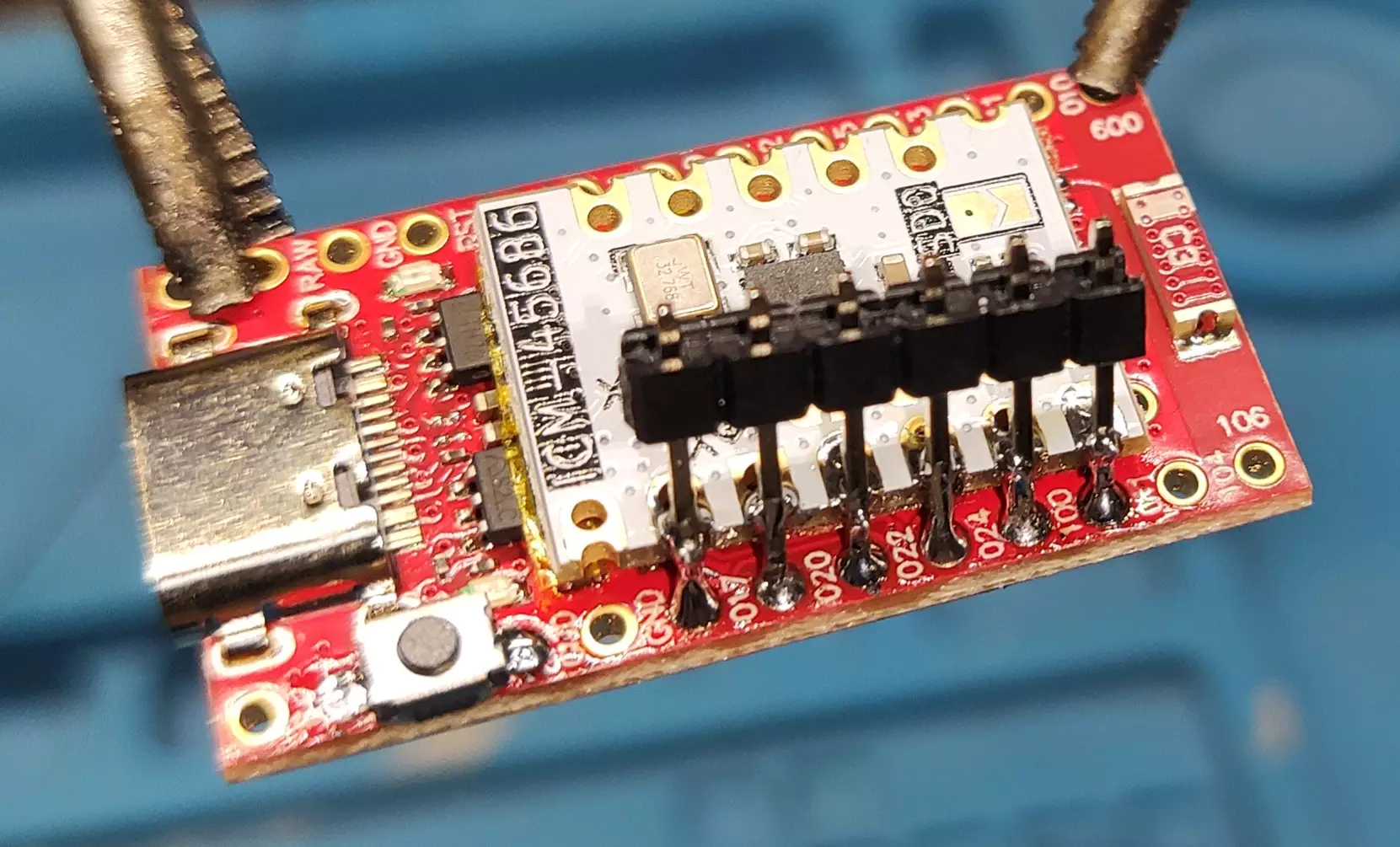
- Solder the headers on the other side at a slight angle so they make solid contact with the IMU pads.
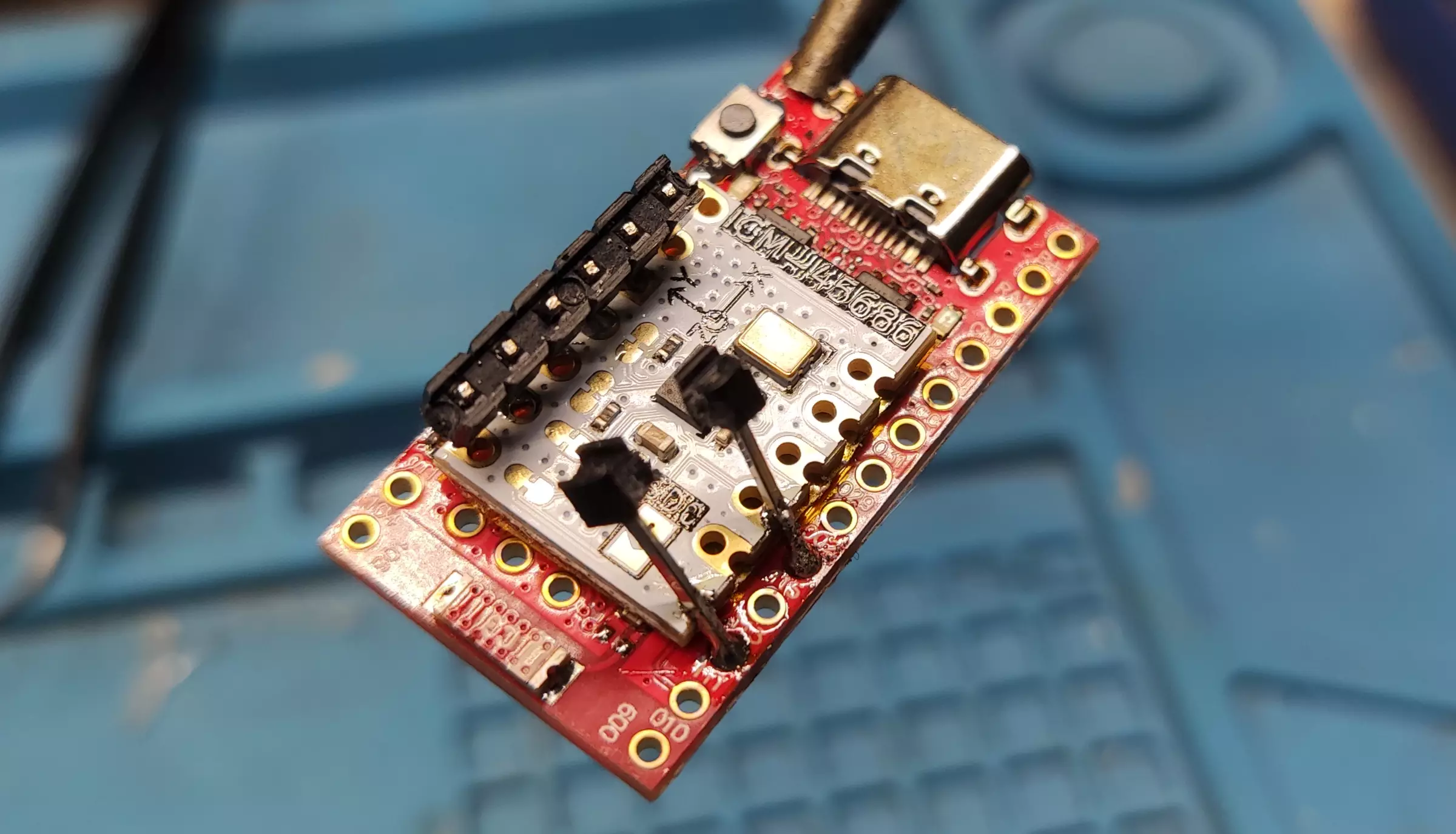
-
Trim and Inspect Header Pins
- Use side cutter pliers to trim excess length from the header pins.
- Inspect the solder joints and add more solder if needed, but avoid overheating, as this can loosen the pins.
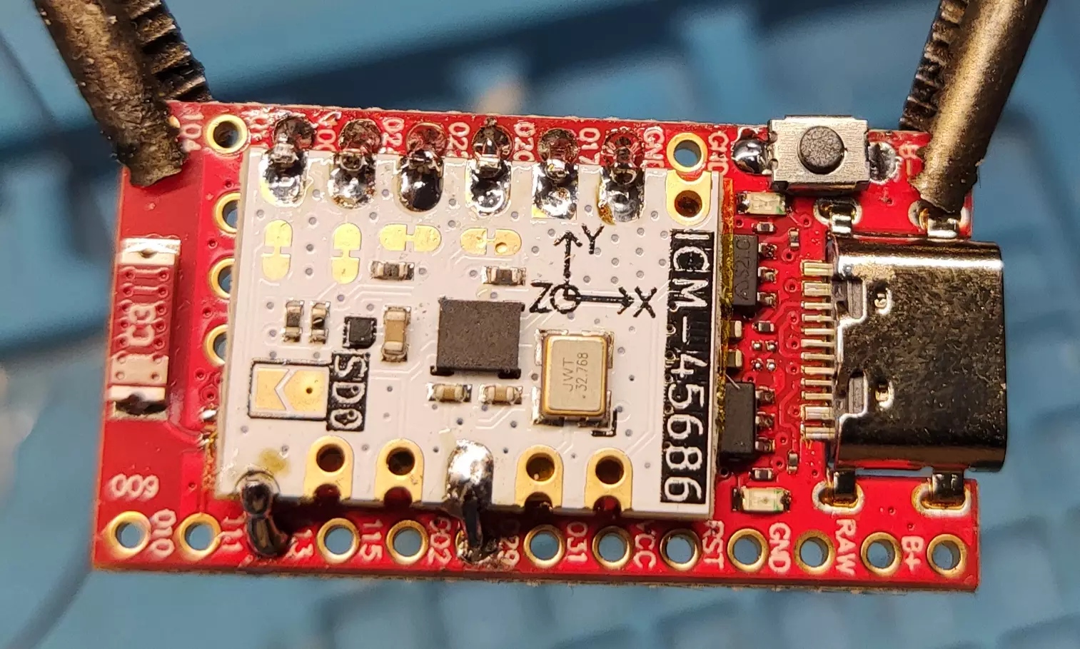
-
Solder the Antenna Mod and Battery
- Solder the antenna wire and the battery leads to their respective pads.
- For optimal performance, the antenna wire should be cut to 31.2 mm. Any deviation will reduce performance.
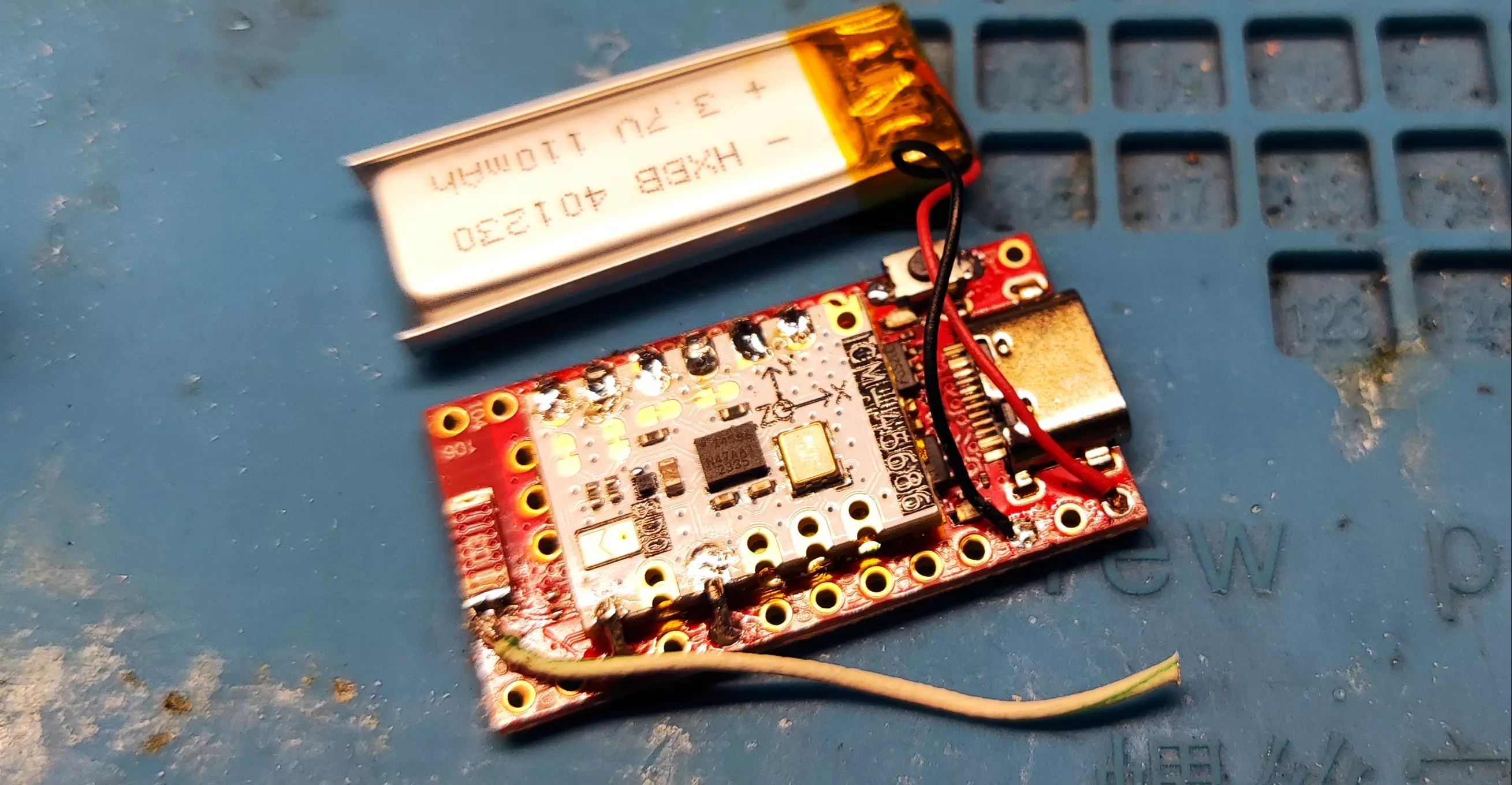
Double-check each connection carefully before powering the board.
Use the info command in a serial terminal to check if the IMU is detected. If it is not detected, this usually means there is a soldering issue, or less commonly, a hardware fault.
Additional Materials
Ibis Soldering Fixture
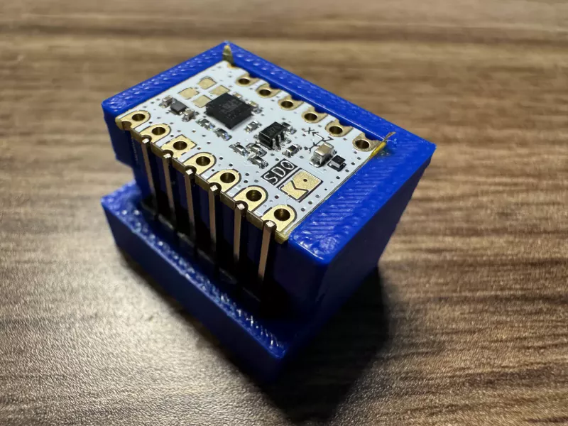
You can optionally use the Ibis soldering fixture to hold your IMU and headers securely in place while soldering. Note: That this fixture does not work for every IMU, as it is specifically designed for the LSM6DSR/LSM6DSV from Deyta's Moffshop and ICM-45686 from SlimeVR Store.
Created by Shine Bright ✨ and Depact
Smol Firmware
This section provides an overview of the firmware used in Smol Slimes trackers and receivers, with links to detailed guides.
What you'll find in this section
-
Pre-Compiled Firmware Download links and instructions for using pre-built firmware images for common hardware and pin configurations. This section also includes custom bootloaders (UF2 and HEX) compiled specifically for SlimeVR trackers and receivers.
-
Flashing Firmware Instructions for flashing firmware onto supported boards and dongles, including both UF2 and Nordic-based bootloader methods.
-
SmolSlimeConfigurator Pairing and Calibrating your Smol Slimes in one app with a easy UI, On Linux & Windows.
Created by Shine Bright ✨ and Depact
Pre-Compiled Firmware for Default Pins
This is the recommended method of getting the firmware if you don't need custom config or pin defines.
Table Of Contents
Required Tools
You only need the following if you are using precompiled firmware:
- nRF Connect for Desktop (Programmer) for flashing Nordic or eByte Dongles only
- nRF Connect for Desktop (Serial Terminal) for sending commands to your Receiver/Trackers, see alternatives
- Or SmolSlimeConfigurator, an all-in-one programming and configuration tool for your Smol Slimes.
- SlimeVR Server
- 0.13.2 or later version
Recommended Bootloader
On ProMicro boards, 2.1V bootloader is generally recommended because it is more power efficient.
However, some components (such as the QMC6309 magnetometer) may not operate correctly at this voltage, in which case you must use the 3.3V bootloader instead.
Important compatibility notes
- You can re-flash from 3.3V → 2.1V using the UF2 bootloader.
- You cannot re-flash from 2.1V → 3.3V using UF2 alone.
- This requires an SWD debugger (see: SWD debugging).
💿 Bootloader
| Device | 2.1V UF2 | 2.1V HEX | 3.3V UF2 | 3.3V HEX |
|---|---|---|---|---|
| ProMicro | Link | Link | Link | Link |
| XIAO | Link | Link | Link | Link |
| R3 | Link | Link | — | — |
| Butterfly P1 | Link | Link | — | — |
| Butterfly P2 | Link | Link | — | — |
| Butterfly P3, R6 | Link | Link | — | — |
| Butterfly P3, R7 | Link | Link | — | — |
Latest Builds Firmware (Automated)
📡 Receiver
🏃 Tracker
Tracker Firmware Options Explained
| Option | Values | Meaning | Recommended |
|---|---|---|---|
| Protocol | SPI/I2C |
Communication method between the microcontroller and IMU sensor.
|
SPI |
| Clock | On/Off |
Whether the attached IMU uses an external clock.
|
✅ (When hardware supports external clock) |
| Sleep (WOM) | ✅/✖️ |
WOM stands for Wake-On-Motion mode.
|
✖️ (Unless battery life is the absolute highest priority) |
| SW0 Enabled (button) | N/A |
Firmware compiled with button support. Allows physical button input for tracker control. |
If your hardware has a button. |
| SW0 Disabled (no button) | N/A |
Firmware compiled without button support. No functionality assigned to physical button presses. |
Non-standard option. |
🥪 Stacked
| Device | Protocol | Clock (ICM) | Sleep (WOM) Wake On Motion. |
SW0 Disabled
(no button) |
SW0 Enabled
(button) |
|---|---|---|---|---|---|
| ProMicro | SPI | ✅ | ✅ | N/A | Link |
| ✖️ | N/A | Link ✅ recommended | |||
| I2C | ✅ | N/A | Link | ||
| ✖️ | N/A | Link | |||
| ProMicro | SPI | ✖️ | ✅ | N/A | Link |
| ✖️ | N/A | Link | |||
| I2C | ✅ | N/A | Link | ||
| ✖️ | N/A | Link |
Normal (Non-Stacked)
| Device | Protocol | Clock (ICM) | Sleep (WOM) Wake On Motion. |
SW0 Disabled
(no button) |
SW0 Enabled
(button) |
|---|---|---|---|---|---|
| ProMicro | SPI | ✖️ | ✅ | Link | Link |
| ✖️ | Link | Link | |||
| ✅ | ✅ | Link | Link | ||
| ✖️ | Link | Link | |||
| I2C | ✖️ | ✅ | Link | Link | |
| ✖️ | Link | Link | |||
| ✅ | ✅ | Link | Link | ||
| ✖️ | Link | Link | |||
| XIAO | I2C/SPI | ✖️ | ✅ | Link | Link |
| ✖️ | Link | Link | |||
| ✅ | ✅ | Link | Link | ||
| ✖️ | Link | Link | |||
| R3 | I2C | ✅ | ✅ | Link | N/A |
| ✖️ | Link | N/A | |||
| Butterfly (P1) | I2C | ✅ | ✅ | Link | N/A |
| ✖️ | Link | N/A | |||
| Butterfly (P2) | I2C | ✅ | ✅ | Link | N/A |
| ✖️ | Link | N/A | |||
| Butterfly (P3, R6) | I2C | ✅ | ✖️ | Link | N/A |
| Butterfly (P3, R7) | I2C | ✅ | ✖️ | Link | N/A |
| Butterfly (P4, R8) | SPI | ✅ | ✖️ | N/A | Link |
| Butterfly (P4, R9) | SPI | ✅ | ✖️ | N/A | Link |
⚙️PCB
| Device | Protocol | Clock (ICM) | Sleep (WOM) Wake On Motion. |
SW0 Disabled
(no button) |
SW0 Enabled
(button) |
|---|---|---|---|---|---|
| Chrysalis | SPI | ✅ | ✅ | N/A | Link |
| ✖️ | N/A | Link |
Previous Firmware Builds
Previous builds can be found here: https://github.com/Shine-Bright-Meow/SlimeNRF-Firmware-CI/actions
- Click on a successful workflow run ✅ for the specified date range.
- Scroll down to the Artifacts section.
- Download the desired device firmware.
- Extract the ZIP file.
Created by Shine Bright ✨, Depact and Seneral
Smol Flashing Bootloader and Firmware
Table of Contents
- Flashing Boards with Adafruits UF2 Bootloader (ProMicro / XIAO)
- Flashing Dongles with SoftDevice/Nordic Bootloader (eByte/Nordic/Holyiot)
Flashing Boards with Adafruits UF2 Bootloader (ProMicro / XIAO)
Flashing the Bootloader
- For the ProMicro, download update-slimenrf_promicro_bootloader-0.9.2-SlimeVR.7_nosd.uf2. For the XIAO, download update-slimenrf_xiao_sense_bootloader-0.9.2-SlimeVR.7_nosd.uf2.
- Connect the device to your computer using a USB data cable.
- The device should initially start in DFU mode when new and without a bootloader. The LED should fade on and off.
- If the device's LED is not fading on and off, press the reset button twice (or briefly short the RST and GND pins) twice within 0.5 seconds. If the device has existing SlimeNRF firmware, reset it four times.
- Navigate to your Downloads folder and copy the UF2 file.
- Navigate to the Mass Storage Drive (ex. NICENANO/XIAO-SENSE) from ThisPC.
- Paste the file there, and the window should close, causing the device to reboot.
Update the bootloader on your ProMicro and XIAO boards before flashing the firmware; otherwise, there is a significant risk of bricking your device. eByte and Nordic dongles are not included in this category.
Flashing the Firmware using UF2
- Connect the device to your computer using a USB data cable.
- The device should initially start in DFU mode when new and without a bootloader. The LED should fade on and off.
- If the device's LED is not fading on and off, press the reset button twice (or briefly short the RST and GND pins) twice within 0.5 seconds. If the device has existing SlimeNRF firmware, reset it four times.
- Obtain the fimware:
- For local builds, navigate to the local Receiver or Tracker repository, then go to
build\REPOSITORY_NAME\zephyr\and copy the "zephyr.uf2" file. - Alternatively, use the pre-compiled firmware.
- For local builds, navigate to the local Receiver or Tracker repository, then go to
- Navigate to the Mass Storage Drive (ex. NICENANO/XIAO-SENSE) from ThisPC.
- Paste the file there, and the window should close, causing the device to reboot.
Flashing the Firmware using adafruit-nrfutil
This uses the bootloaders serial protocol to flash it using command line tools.
See Adafruit nRF52 nrfutil Github Repo for install and usage instructions.
Recommended: Use a python venv to install the adafruit-nrfutil python tool.
Flashing Dongles with SoftDevice/Nordic Bootloader (eByte/Nordic/Holyiot)
This bootloader will appear as "Open DFU Bootloader" by Nordic Semiconductor. Currently, the only confirmed method for flashing firmware onto these devices is through nRF Connect for Desktop, though it should also be possible to use nRF Util (but it is more complex and practically equivalent).
NOTE: Installing the Segger J-Link is not required for this bootloader.
NOTE: On Linux, nRF Connect for Desktop installs nodeJS tools into ~/.nrfconnect-apps/, nRF Util installs binary tools into ~/.nrfutil/.
Flashing using nRF Connect for Desktop
- Open "Programmer" in the nRF Connect.
- Put the device into DFU mode using either of these methods:
- Press the reset button — the LED should begin to fade on and off, indicating the device is in DFU Mode. For the eByte dongle, this is the right button. For the Nordic dongle, it is the side button (not the round white button).
- For the HolyIOT-21017 Dongle, place the provided magnet (from the USB port) near the LED area. The red LED should begin fading on and off.
- For Receivers with pre-existing SlimeNRF Firmware flashed, open the Serial Terminal in nRF Connect and enter
dfu. (This only works for some Open DFU Bootloader Devices)
- In the top left corner, select your Device.
- Click on "Add File".
- Select the firmware (.hex) you want to flash:
- For local builds, navigate to your local Receiver repository, then select the file located at
build\REPOSITORY_NAME\zephyr\zephyr.hex. - Alternatively, use pre-compiled firmware.
- For local builds, navigate to your local Receiver repository, then select the file located at
- Click the "Write" button. If a udev error prevents the write, follow this guide; you may need to use the alternative method provided.
Flashing using nRF Util
Not documented yet. Relevant documentation:
Created by Shine Bright ✨, Depact, Seneral, and Kresny
Smol Updating Firmware
Required Tools
You only need the following if you are using precompiled firmware:
- nRF Connect for Desktop (Programmer) for flashing Nordic or eByte Dongles only
- nRF Connect for Desktop (Serial Terminal) for sending commands to your Receiver/Trackers, see alternatives
- Or SmolSlimeConfigurator, an all-in-one programming and configuration tool for your Smol Slimes.
- SlimeVR Server
- 0.13.2 or later version
Steps
For flashing new trackers and receivers, check the Flashing Firmware Guide.
- Download the latest firmware version from Pre-Compiled Firmware.
- Connect your tracker to your computer via USB, and ensure it is powered on.
- Run the
dfucommand in your terminal. - Your tracker will appear as a USB drive labelled
SLIMENRFTRKorNICENANOetc. (depending on your tracker hardware) - Copy the UF2 firmware file to your tracker.
- If your tracker isn't paired after update, see Adding More Trackers.
A Windows error after copying firmware is common and does not mean it failed. Check the commit version in the terminal if you are unsure.
Be sure to flash the correct firmware version! Incorrect firmware can cause your tracker to become unresponsive.
Created by Shine Bright ✨, Depact and Seneral. Edited by Brisfknibis.
SmolSlimeConfigurator
Pure Simple UI Configurator for SlimeVR Smol Slimes (Unofficial) Github page: SmolSlimeConfigurator
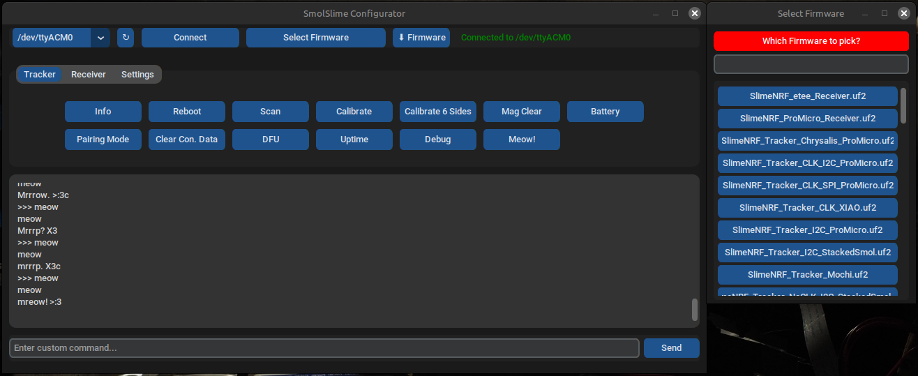
Features
- Easy-to-use interface — clean, modern, simple to use, with helpful tooltips.
- Effortless configuration — one-click buttons for calibration, pairing, and more.
- Automatic firmware updater — plug your tracker in via USB, select your firmware type, and flash the latest build instantly.
- Always up to date — the firmware list automatically fetches the latest daily builds from GitHub.
- Custom firmware support — flash your own
.uf2or.hexfiles with ease (now supports all dongles and trackers). - Favorites system — star your most-used firmware versions by right-clicking (middle-click on macOS).
- Cross-platform — available for Windows, Linux, macOS, and Android.
- Theme customization — switch between light/dark mode and choose your favorite accent color.
Download
There are two options to run the Configurator:
- Single-file executables are available from Releases (Windows, Linux, macOS, Android).
- Python file from the uploaded files above.
- To build it from source, run:
pyinstaller --onefile --windowed --icon=icon.png --add-data "icon.png:." --add-binary "/Location/To/UR/NameOfVenv/bin/nrfutil:." SmolSlimeConfiguratorV8.py
Note: You must use a virtual environment, must use Python 3.10.x, and change the icon file extension to .icns on macOS or .ico on Windows.
Instructions
Note: There is a video tutorial explaining general usage, and this video covers Android usage in detail.
First install
- Plug in the tracker or receiver and press reset twice. On boards without a reset button, hold one side of a wire on the RST pin
 and double-tap a GND pin (the USB-C connector on the Nice!Nano/ProMicro)
- Press "↻" refresh, then select the port from the dropdown menu on the left of the refresh button, then press "Connect"
- Select the version of hardware from the dropdown menu called "Select Firmware", press "⬇ Firmware", Wait ~20 seconds, the tracker will flash.
Pairing
- Plug in your receiver, press "↻" refresh, select the port, then press "Connect".
- To configure your receiver, select the receiver tab, press pairing mode, and power on each receiver one by one. You should notice
 the trackers being added. Once all trackers have been paired, press "Exit Pairing Mode".
Calibration
- Plug in a tracker, press "↻" refresh, select the COM port, and press "Connect". Press "Calibrate 6 Sides" and follow the terminal instructions.
- Then press "Calibrate", leave the tracker on a desk for ~5 seconds, and you're done! Note: You can also double-tap the tracker's button instead of pressing "Calibrate".
Updating Firmware
- Connect to the port, select the firmware, press "⬇ Firmware" and wait ~20 seconds.
Note: Trackers and receivers must all be updated to the same version, or they will not pair.
Smol Compiling Firmware
This is the method of compiling firmware if pre-compiled firmware for default pins doesn't fit your needs.
This page contains step-by-step guide for building the firmware from source, including required tools, repository setup, and build instructions.
Table of Contents
- Required Tools
- Cloning Repositories
- Building Firmware using nRF Connect for VS Code
- Building Firmware Manually (Linux)
- Protocols
- Troubleshooting
- Links
Required Tools
For those interested in building the firmware yourself:
- Git Client
- nRF Connect for Desktop with various integrated tools:
- Programmer (for flashing Nordic and eByte Dongles only)
- Serial Terminal (for sending commands to your Receiver/Trackers, see alternatives)
- NOTE: Installing the Segger J-Link is not necessary for pre-defined boards.
- VS Code (For development purposes only)
- nRF Connect for VS Code by Nordic Semiconductor
- Install from VS Code Extension tab.
- Open nRF Connect tab.
- SDK
- Click "Install SDK".
- Select "nRF Connect SDK".
- Select "v3.1.1".
- Press "Enter" key to install in default location.
- Click "Install".
- Toolchain
- Click "Install Toolchain".
- Select "v3.1.1".
- Install from VS Code Extension tab.
- You may also set up a manual build environment in VS Code as the extension is known to fail on some certain Linux distributions.
- nRF Connect for VS Code by Nordic Semiconductor
- SlimeVR Server
- 0.13.2 or later version
Cloning Repositories
- Open the Command Prompt by typing
cmdin the Start Menu. - Navigate to the directory where you want to clone the repositories.. (Type "cd" followed by a space and then the full path to the desired folder or drive.)
- Cloning SlimeNRF Receiver Repository.
git clone --recurse-submodules https://github.com/SlimeVR/SlimeVR-Tracker-nRF-Receiver.git
- Cloning the SlimeNRF Tracker Repository.
git clone --recurse-submodules https://github.com/SlimeVR/SlimeVR-Tracker-nRF.git
If you're using an existing case design, you can opt for prebuilt firmware; otherwise, build your own. See Smol Firmware for more details.
Note: It is recommended to clone to a file path that does not contain whitespace or Unicode characters. You may encounter errors when building the firmware.
Building Firmware using nRF Connect for VS Code
ProMicro Build Variants
I2C: Edit promicro_uf2.dts and build using promicro_uf2/nrf52840/i2c.
SPI: Edit promicro_uf2.dts and build using promicro_uf2/nrf52840/spi.
- Open the folder for one of the repositories.
- Make any pin changes or necessary adjustments to
boards\MANUFACTURER\BOARD_NAME.dts. - Click on the nRF Connect tab located on the left side of your screen, approximately halfway down.
- Under "Applications" , click on "+ Add build configuration."
- Select
3.1.1for the SDK and Toolchain drop-down menu. - Select a preset from the "Board Target".
- Scroll down and click the "Build Configuration" button.
Note: For trackers, settings can be found in the "nRF Kconfig GUI" under "Actions" and expand the "SlimeNRF" section.
Changing Board Defines
Board defines can be found in \boards\ for overlays (Boards within the Zephyr library), while custom boards are located in boards\MANUFACTURER\BOARD_NAME.dts.
- Navigate to the board's .dts file.
- The I2C (SCL/SDA) lines can be assigned to different pins. Ensure that you are using "High Frequency" pins and that you change the pins for both lines accordingly.
- SW0 can be enabled by uncommenting (removing the
//) from the lines below the description comment. If you are using VS Code, you can select the lines and press Ctrl / if you are using VS Code. Additionally, redefine the GPIO pin if necessary. - The INT (int0-gpios) can be redefined in the Zephyr user section.
- The CLK (clk-gpios) can be uncommented and redefined if you are using an IMU with an external clock or crystal oscillator, such as the ICM-42688 or ICM-45686.
Adjusting settings in the Kconfig
- Navigate to the nRF Connect tab of VS Code.
- Build the desired board once.
- A section titled Actions should be displayed on the left navigation panel.
- Select your built board under Applications, then scroll down to the Actions section.
- Double-click nRF Kconfig GUI.
- Scroll down to the SlimeNRF section.
- Enable or disable any necessary configurations, or adjust them as needed.
- Click the "Apply" button, then click the "Save to File" button.
- If prompted to select a file to save, choose prj.conf.
- Click the "Pristine Build" button located next to Build in the Actions section.
Building Firmware Manually (Linux)
This is only recommended if you are experiencing issues with nRF Connect for VS Code, as you will need to manually set up the toolchain.
Setup Python Venv
Using a virtual environment (venv) will keep all build tools for Zephyr, such as west, contained.
python3 -m venv ~/.venv/nrf52
source ~/.venv/nrf52/bin/activate (Run the setup whenever you use or modify it.)
pip3 install west
Setup nRF Connect SDK code
Please select an appropriate folder for installing the toolchain, such as ~/.toolchain-nrf52.
Then execute:
west init -m https://github.com/nrfconnect/sdk-nrf --mr v3.1.1 nrf52-sdk-3.1.1
cd nrf52-sdk-3.1.1
west update (This will download dozens of Git repositories; it may take some time.)
pip install -r zephyr/scripts/requirements-base.txt (Install the remaining requirements for building.)
west zephyr-export (This will register the necessary CMake files in your home directory.)
If you move this folder, you simply need to re-run the last command.
Setup Zephyr SDK
The nRF Connect SDK depends on the Zephyr SDK, so please return to your toolchain folder (e.g. ~/.toolchain-nrf52) to install it:
wget -q https://github.com/zephyrproject-rtos/sdk-ng/releases/download/v0.17.4/zephyr-sdk-0.17.4_linux-x86_64_minimal.tar.xz
tar xf zephyr-sdk-0.17.4_linux-x86_64_minimal.tar.xz -C .
cd zephyr-sdk-0.17.4
./setup.sh -c -t arm-zephyr-eabi (This will register the necessary CMake files in your home directory.)
If you move this folder, you simply need to re-run the last command.
Compiling Manually
Assuming your toolchain is installed in ~/.toolchain-nrf52 and you are in the firmware directory:
source ~/.venv/nrf52/bin/activate
source ~/.toolchain-nrf52/nrf52-sdk-3.1.1/zephyr/zephyr-env.sh
west build --board BOARD --build-dir build . -- -DNCS_TOOLCHAIN_VERSION=NONE -DBOARD_ROOT=.
Replace BOARD with your specific board (e.g. promicro_uf2/nrf52840 for the ProMicro, nrf52840dongle/nrf52840 for a dongle receiver).
The compiled firmware will be located at PROJECT_DIR/build/PROJECT_DIR/zephyr/zephyr[.hex|.uf2].
Compiling with VS Code (Without Extensions)
Assuming your toolchain is installed in ~/.toolchain-nrf52, use the following tasks, which should be placed in .vscode/tasks.json:
{
    "version": "2.0.0",
    "tasks": [
        {
            "label": "Build",
            "type": "shell",
            "group": "build",
            "command": "source",
            "args": [
                "~/.venv/nrf52/bin/activate", "&&",
                "source", "~/.toolchain-nrf52/nrf52-sdk-3.1.1/zephyr/zephyr-env.sh", "&&",
                "west", "build", "--board", "BOARD", "--build-dir", "build",
                "${workspaceFolder}", "--",
                "-DNCS_TOOLCHAIN_VERSION=NONE", "-DBOARD_ROOT=${workspaceFolder}"
            ]
        },
    ]
}
Replace BOARD with your specific board (e.g. promicro_uf2/nrf52840 for the ProMicro, nrf52840dongle/nrf52840 for a dongle receiver).
The compiled firmware will be located at PROJECT_DIR/build/PROJECT_DIR/zephyr/zephyr[.hex|.uf2].
Protocols
This section offers advanced information about the communication protocol and is not necessary for building your own smol slimes.
HID Protocol
The HID Protocol is not finalized and is subject to change in future versions of the SlimeVR Server.
Tracker -> Server
b0      |b1      |b2      |b3      |b4      |b5      |b6      |b7      |b8      |b9      |b10     |b11     |b12     |b13     |b14     |b15     |
type    |id      |packet data                                                                                                                  |
0       |id      |proto   |batt    |batt_v  |temp    |brd_id  |mcu_id  |imu_id  |mag_id  |fw_date          |major   |minor   |patch   |rssi    | info
1       |id      |q0               |q1               |q2               |q3               |a0               |a1               |a2               | full precision quat
2       |id      |batt    |batt_v  |temp    |q_buf                              |a0               |a1               |a2               |rssi    | reduced precision quat
3       |id      |svr_stat|status  |resv                                                                                              |rssi    | status
4       |id      |q0               |q1               |q2               |q3               |m0               |m1               |m2               |
255     |id      |addr                                                 |resv                                                                   |
Tracker <-> Receiver
b0      |b1      |b2      |b3      |b4      |b5      |b6      |b7      |b8      |b9      |b10     |b11     |b12     |b13     |b14     |b15     |
type    |id      |packet data                                                                                                                  |
64      |id      |addr                                                 |resv                                                                   | pairing data from tracker
65      |id      |addr                                                 |addr_rcv                                             |channel |resv    | pairing data to tracker
66      |id      |addr                                                 |time                                                                   | timing data to tracker (why addr?)
67      |id      |addr                                                 |cmd_data                                                               | some command to tracker? (need to be part of timing?)
Tracker <-> Server
b0      |b1      |b2      |b3      |b4      |b5      |b6      |b7      |b8      |b9      |b10     |b11     |b12     |b13     |b14     |b15     |
type    |id      |packet data                                                                                                                  |
128     |id      |addr                                                 |cmd_data                                                               | some command to tracker? (field too large?)
128     |id      |addr                                                 |ack                                                                    | acknowledge?
Receiver <-> Server
b0      |b1      |b2      |b3      |b4      |b5      |b6      |b7      |b8      |b9      |b10     |b11     |b12     |b13     |b14     |b15     |
type    |id      |packet data                                                                                                                  |
192     |id      |resv                                                                                                                         | 192+ should be some interaction b/w receiver and server
254     |resv                                                                                                                                  | filler, this packet is ignored by the server
255     |id      |addr                                                 |resv                                                                   | tracker id association
Troubleshooting
Please open a GitHub issue for any firmware bugs or issues in the corresponding repositories.
Check Console Logs
- Launch nRF Connect for Desktop.
- Open the Serial Terminal in nRF Connect.
- Ensure that your tracker is connected to your computer using a cable.
- In the top left corner, select your tracker under Devices.
- Click the "Connect to Port" button.
Improving Logging
-
In order to change the log level you see (e.g., LOG_DBG instead of just LOG_INF), you may need to edit the
LOG_MODULE_REGISTERmacro at the top of the relevant module or file you are interested in and then recompile the firmware. -
If you need to view the logs prior to connecting to the serial console, you may need to explicitly initiate the logging backend by adding the following code snippet in the main function of main.c:
const struct log_backend *backend = log_backend_get_by_name("log_backend_uart");
log_backend_enable(backend, backend->cb->ctx, CONFIG_LOG_MAX_LEVEL);
Additionally, add the following include to the top of the main.c file:
#include <zephyr/logging/log_ctrl.h> -
If you notice that the logs are truncated at a certain point, the buffer size may be insufficient. This issue has not been fully resolved yet, as simply increasing
CONFIG_LOG_BUFFER_SIZEinprj.confdoes not appear to be effective.
SWD Debugging
- Instructions for the Raspberry Pi, Raspberry Pi Pico, ST-Link V2, and other debuggers will be added in the future. Resource: https://github.com/joric/nrfmicro/wiki/Bootloader
J-Link, nRF52/nRF52840 Development Kit, and OB-ARM Debugger
- Install J-Link Software and Documentation Pack: https://www.segger.com/downloads/jlink/#J-LinkSoftwareAndDocumentationPack
- Download Bootloader HEX File for your device (ProMicro - slimenrf_promicro_bootloader-0.9.2-SlimeVR.7_s140_7.3.0.hex, XIAO - slimenrf_xiao_sense_bootloader-0.9.2-SlimeVR.7_s140_7.3.0.hex)
- Connect Debugger to SWD IO, CLK, and GND Pins. (It is safer to power up your device by plugging into USB instead of using the VDD pin)
Flashing/Fixing bricked bootloader
- Launch "J-Flash Lite."
- Target Device: NRF52840_XXAA
- Target Interface: SWD
- Speed: 4000
- Click the "OK" button.
- Click on the "..." button and select the downloaded HEX file.
- Click the "Program Device" button.
RTT/Debugging
- Launch "RTT Viewer."
- Connection to J-Link: USB
- Specify Target Device: NRF52840_XXAA
- Force go on connect: Checked
- Target Interface & Speed: SWD / 4000 hKz
- RTT Control Block: Auto Detect
- Click the "OK" button.
Recommended Hardware/Tools
OB-ARM Debugger: https://www.aliexpress.us/item/3256806507382540.html
Pogo Pin Test Clip (1.5mm Pitch, 4P, Single Row): https://www.aliexpress.us/item/3256805646654844.html
Note: This clip is designed exclusively for ProMicro. While there are less expensive clips available, they do not convert the pins from a 1.5mm pitch to a 2.54mm pitch suitable for Dupont wires.
Links
Firmware Source Code
Community Firmware
| Name | Author | Description | Links |
|---|---|---|---|
| Stacked-SmolSlime | LyallUlric | Fork of main branch with firmware tailored for stacked ProMicro trackers. | Github |
Created by Shine Bright ✨, Depact and Seneral
Smol LED Codes
Table Of Contents
Standard operation codes
While not plugged in:
| LED State | Status |
|---|---|
| Very short Blinking | Normal Operation Or Wake On Motion |
| 1 Long Blink per second | Low battery |
| Off | Deep sleep or dead battery |
While plugged in:
| LED State | Status |
|---|---|
| Pulsing | Charging |
| Off | Fully charged |
Pairing and flashing codes
| LED State | Status |
|---|---|
| 1 Short Blink per second | Pairing mode |
| Fading on and off | DFU (firmware flash) mode |
Error codes
| LED State | Status |
|---|---|
| 2 Long Blinks every 5 seconds | Sensor error (see below) |
| 3 Long Blinks every 5 seconds | Connection error |
| 4 Long Blinks every 5 seconds | Hardware error |
Troubleshooting Sensor Error
Check info command output. If it contains IMU: None and the IMU is soldered, then there is no continuity on one of the solder points or the IMU is soldered in the wrong position.
If the IMU is soldered correctly, try testing continuity with a multimeter or resolder the connections.
Created by Shine Bright ✨, Depact and Seneral, formatted by otter_oasis.
Smol Serial and Button Commands
Receiver Commands
info- Get receiver informationlist- Get paired trackersreboot- Soft reset the receiverpair- Enter pairing modeadd <address>- Manually add a trackerremove- Remove last paired trackerexit- Exit pairing modeclear- Clear stored trackersdfu- Enter DFU bootloaderuptime- Get receiver uptimemeow- Meow!
Tracker Commands
info- Get tracker informationreboot- Soft reset the trackerbattery- Get battery informationscan- Restart sensor scancalibrate- Calibrate sensor ZRO6-side- Calibrate 6-side accelerometermag- Clear magnetometer calibrationpair- Enter pairing modeset <address>- Manually set receiver (Receiver'saddcommand must be completed first)clear- Clear pairing datadfu- Enter DFU bootloaderuptime- Get tracker uptimedebug- Print debug log to troubleshoot tracker or firmwarereset <type>- Reset calibration/stats for "zro", "acc" (6-Sided enabled only), "mag", "bat", or "all"meow- Meow!
Button Shortcuts
- Reset - 1 Press
- Calibration - 2 Presses
- Pairing Mode - Press and Hold for 5s
- DFU Bootloader - 4 Presses
- Deep Sleep - Press and Hold for 1s
Created by Shine Bright ✨, Depact and Seneral. Edited by Brisfknibis.
Smol Pairing & Calibration
This page contains instructions to pair trackers and receivers, calibrate sensors, and use console commands for setup and troubleshooting.
Overview
This guide covers how to pair, calibrate, and update your Smol Slime trackers and receiver. You’ll use a serial terminal (such as nRF Connect or PuTTY) to run setup and troubleshooting commands.
Table of Contents
- Required Tools
- Pairing Trackers (First Time)
- Adding More Trackers
- Calibrate Trackers
- Troubleshooting
- Reference
Required Tools
You’ll need a serial terminal program to send commands to your trackers and receiver.
- Recommended: Download and install nRF Connect for Desktop.
- Install the Serial Terminal module inside it.
- Linux/Mac:
-
(Find your port withsudo screen /dev/ttyACMX 115200sudo dmesg.)
-
- Windows Alternative: PuTTY
Prefer an easy-to-use app? Check out SmolSlimeConfigurator
Pairing Trackers (First Time)
When first flashed, trackers and receivers boot into pairing mode automatically.
- If the devices are not in pairing mode:
- Receiver: Run
pair - Tracker: Hold the SW0 (Function) button for 5 seconds (or short RST/GND 3 times)
- The LED blinks once per second while in pairing mode.
- Receiver: Run
- Watch for
esb_eventoutput in the receiver console:<inf> esb_event: Added device on id 0 with address 95CB23A0FDF7
- Plug the tracker into your computer via USB.
- The tracker’s LED flashes four times once pairing is successful.
- Repeat for all trackers.
- Exit pairing mode by entering
exiton your receiver.
Adding More Trackers
You can pair individual trackers to your receiver one at a time using the add command (on the receiver) and then the set command (on the tracker).
- On the tracker, run:
info - Copy its "Device Address" (e.g.
95CB23A0FDF7). - On your receiver:
add 95CB23A0FDF7(replace the device address with yours). - Copy the pairing ID from the receiver output:
[00:46:06.485,778] <inf> esb_event: Pair the device with D94BDEF1E442005B
- On your tracker:
set D94BDEF1E442005B - Confirm pairing on the tracker — you should see:
[00:30:51.060,028] <inf> esb_event: Paired
- Repeat all steps for each additional tracker.
The tracker LED will stop blinking once paired. Verify it is connected by moving it to appear in SlimeVR Server. If they don't, reboot both trackers/receiver, then exit pairing mode on the receiver.
Calibrate Trackers
Basic Calibration
The basic calibration runs an accelerometer and gyroscope zero rate offset. This is usually all you need. There are two methods. When calibrating, place the tracker flat on a surface and keep it still until the LED indicates completion.
- Method 1: Press the SW0 (Function) button twice, then wait until the LED blinks four times to confirm calibration.
- Method 2: Connect your tracker to your computer and run
calibrate.
6-Sided Calibration
The 6-sided calibration aligns the accelerometer across all six axes. This method requires you to hold the tracker perfectly still on all 6 sides.
- Connect your tracker to your machine while it is powered on.
- Run the
6-sidecommand. - Place the tracker on each side as prompted. The console will tell you when to rotate, or you can watch for the LED success blinks.
You can unplug the cable immediately after executing the 6-side command. When prompted for the final side, it can be easier to disconnect your USB cable and position the side with the USB port on a flat surface.
Incorrect 6-side calibration can make tracking worse! Hold your tracker steady on a flat, stable surface during calibration.
Magnetometer
Magnetometer calibration is disabled by default. When enabled, it runs automatically — no button or command required. Slowly rotate your tracker 360° on each of its six sides while it’s flat on a surface.
The LED will blink when you place it flat on each side and will blink continuously when it is ready to save.
Magnetometers can improve tracking; however, in environments with strong magnetic interference (like metal desks or PCs), performance may worsen.
Troubleshooting
Linux: SlimeVR Server Cannot Detect Receiver
For Linux systems, a udev rule may need to be created for the SlimeVR Server to detect your receiver as an HID device.
Create the rules file:
touch /etc/udev/rules.d/99-hid-dongle.rules
Add the following rules to the file:
sudo tee /etc/udev/rules.d/99-hid-dongle.rules > /dev/null <<'EOF'
SUBSYSTEM=="usb", ATTR{idVendor}=="1209", ATTR{idProduct}=="7690", MODE="0666"
KERNEL=="hidraw*", SUBSYSTEM=="hidraw", ATTRS{idVendor}=="1209", ATTRS{idProduct}=="7690", MODE="0666"
EOF
Ensure it worked:
cat /etc/udev/rules.d/99-hid-dongle.rules
Note: You may need to update the idVendor and idProduct values for your receiver. Use lsusb to find the correct IDs.
Trackers Paired but Not Appearing in SlimeVR Server
- On your receiver:
exit. - Reboot the tracker:
rebootor press the SW0 button. - Reboot the receiver:
reboot. - Ensure the IMU is detected on the tracker:
info.- Functioning:
IMU: ICM-45686 - Non-Functioning/Not Detected:
IMU: None
- Functioning:
Tracker Repeatedly Outputs Serial Warnings <wrn> sensor: No packets in buffer and <wrn> sensor: Sensor interrupt timeout
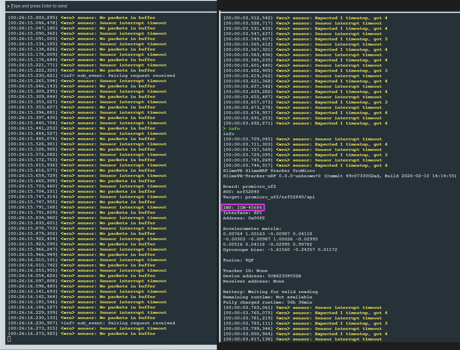
If the tracker repeatedly outputs these warnings:
<wrn> sensor: No packets in buffer
<wrn> sensor: Sensor interrupt timeout
Initial Checks:
- Reboot the tracker using the dedicated reboot button (if available), or by briefly shorting the RST and GND pins.
Diagnostic Steps:
- Run the
infocommand to verify IMU detection.
If IMU detected, solution:
- Check that the
INT1pin is properly soldered. See schematic: Smol Tracker
Reference
Status Codes
Status codes consist of one or more status values (added together) listed below:
| Code | Meaning |
|---|---|
| 1 | SYS_STATUS_SENSOR_ERROR |
| 2 | SYS_STATUS_CONNECTION_ERROR |
| 4 | SYS_STATUS_SYSTEM_ERROR |
| 8 | SYS_STATUS_USB_CONNECTED |
| 16 | SYS_STATUS_PLUGGED |
| 32 | SYS_STATUS_CALIBRATION_RUNNING |
| 64 | SYS_STATUS_BUTTON_PRESSED |
Created by Shine Bright ✨, Depact and Seneral. Edited by Brisfknibis.
SlimeVR Setup
This guide should help you set up SlimeVR trackers and software.
The guide assumes you have either working and flashed DIY trackers, or production trackers. If you are looking for information building your own trackers please jump to our DIY guide page, if you need to flash your tracker's firmware check the firmware guide.
PLEASE NOTE: The follow pages are out of date currently, if you are setting up your trackers for the first time please visit our Quick Setup Guide.
The follow pages assume you are working in a windows environment, if you are on Linux check our Linux page first.
- Initial Setup
- Connecting your Trackers
- Configuring your Trackers
- Putting on your Trackers
- Body Proportions Configuration
- Setting up Reset Bindings
- OSC
- IMU Calibration
- Alternative Wi-Fi Options
Initial Setup
This guide should help you with installing the SlimeVR Server and getting things set up so that everything is functioning as it should.
Install the Latest SlimeVR Installer
The latest SlimeVR Installer can be found here. Download it and install it, this installer can be used to update the server software in the future.
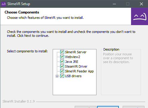
Bear in mind, if you plan on using the server purely for standalone usage via OSC, and not PC VR via SteamVR, you can de-select SteamVR Driver, SlimeVR Feeder App, and USB drivers. If you don't already have SteamVR installed and have launched it previously, you may encounter an error.
Test Your Trackers
Turn each tracker on and see if they work.
Each tracker should blink an LED briefly on startup, and then blink every few seconds to indicate its status as follows:
| Number of blinks | Status |
|---|---|
| 1 | Tracker is ready |
| 2 | Connecting to SlimeVR server |
| 3 | Connecting to wifi |
| 5 | IMU error |
If a tracker doesn't start up, try charging it. Connect the tracker via USB port to your PC or any USB charger. A red LED light should light up to indicate that it's charging. A green LED or blue LED light means it's fully charged (LED might be a different colour depending on your charging board). Try turning the tracker on during charging to see if it works.
Please note that as a rule, DIY trackers should be kept off while charging outside of this specific case.
IMU Calibration
Depending on what IMU you are using, you will need to calibrate them in different ways. To find out how to calibrate your IMU, go to the IMU Calibration page.
Check that the Driver Loads and Connects
-
Start SteamVR, go to Settings > Manage Add-Ons. Check if SlimeVR exists here, set it to On.
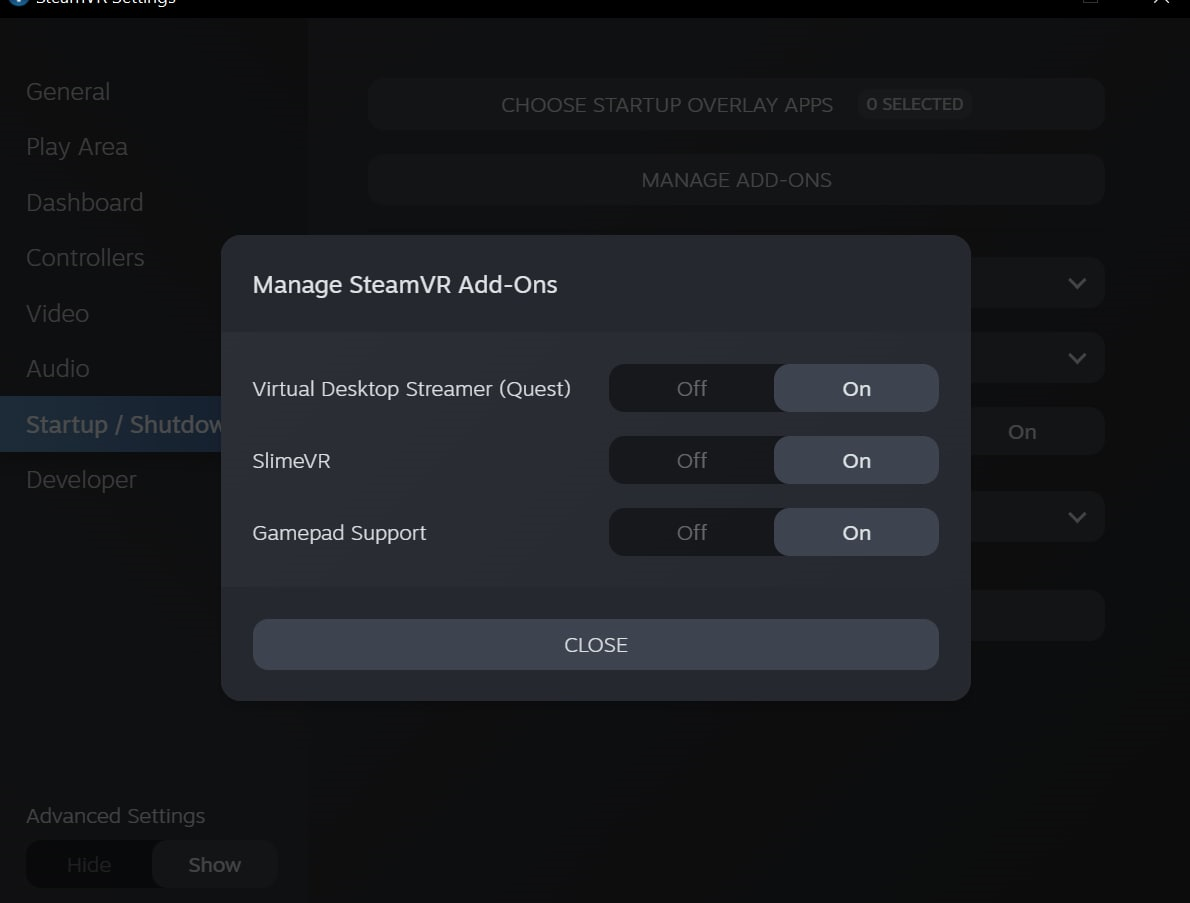
-
Start the SlimeVR Server through the start menu via the "SlimeVR Server" shortcut.
-
Restart SteamVR. Now you should see 3 trackers active in SteamVR:
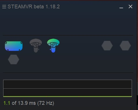
-
In SlimeVR Server, you should see the rotation change for your headset and controllers as you move them around:
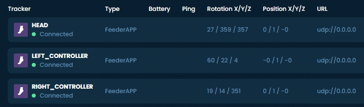
Created by Eiren, edited by adigyran, calliepepper, emojikage and nwbx01, styled by calliepepper.
Connecting your Trackers
This guide should help you set up SlimeVR trackers and software.
Connecting trackers
Note: If you are using DIY trackers with hardcoded the WiFi credentials or phones with owoTrack, you can skip to assigning your trackers. However, if you hardcoded the WiFi credentials and are having trouble connecting these steps may still be helpful for diagnosing the issue.
-
Open the SlimeVR Server and click Setup Wizard, please note if required you can change the displayed language at this point at the bottom right.
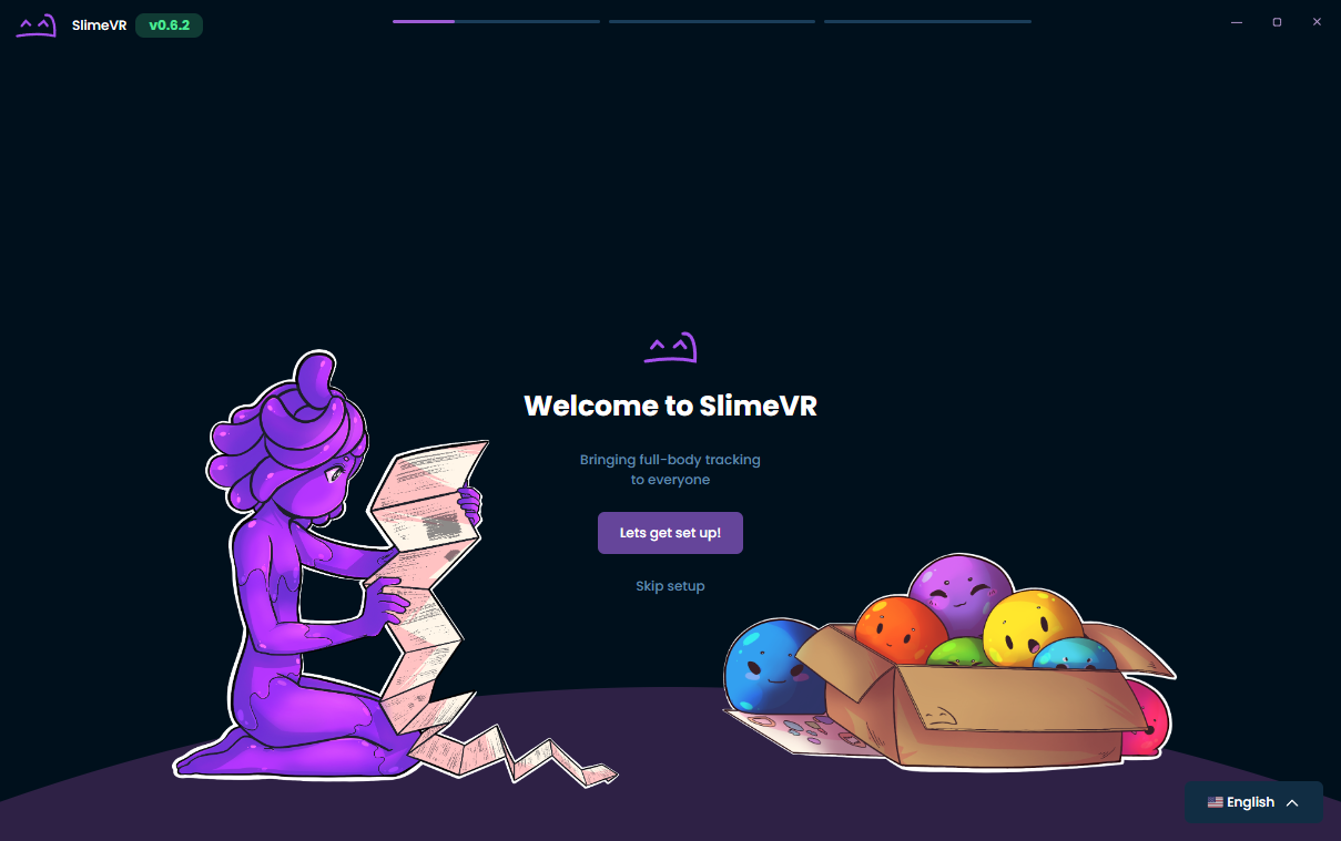
-
Input your WiFi credentials, so that your tracker can connect to WiFi, then click Submit.
BEWARE If you use official trackers make sure to turn them on for this process!
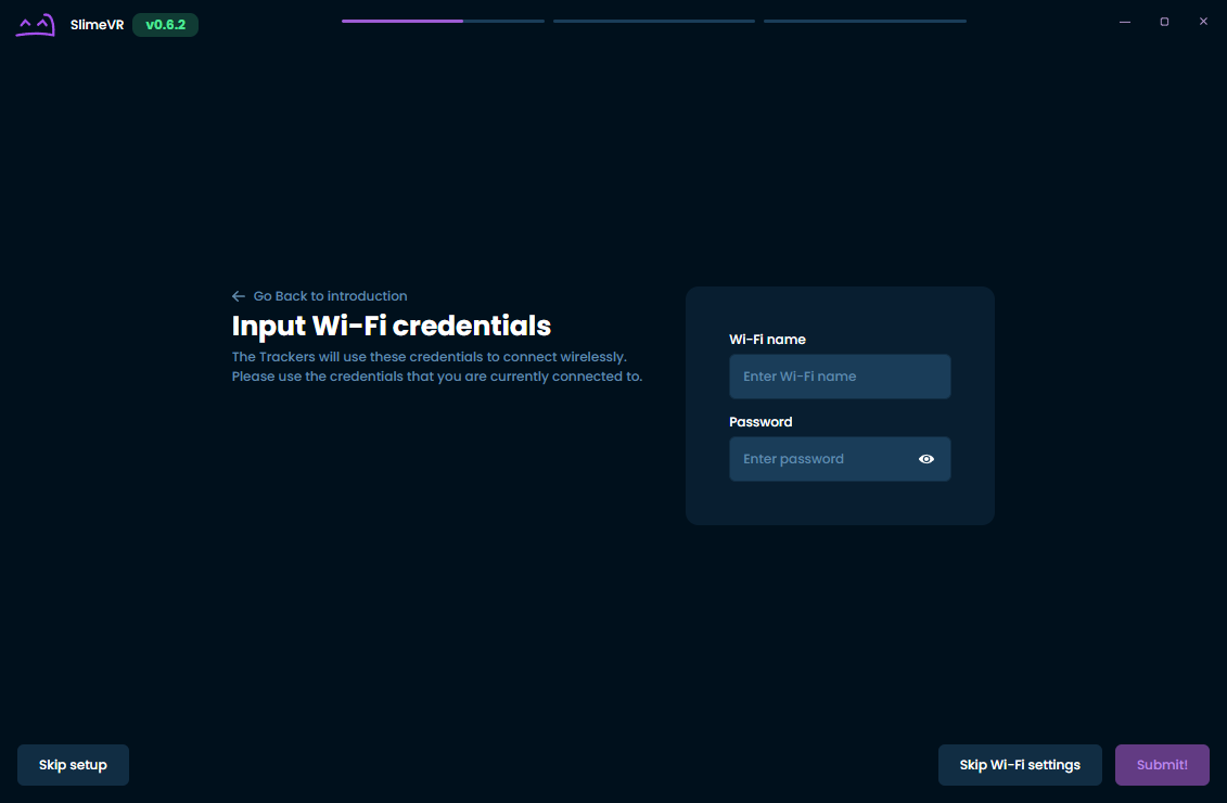
-
Plug in a tracker one at a time. You should then see your tracker appear after a little while. Click I connected all my trackers once you're done.
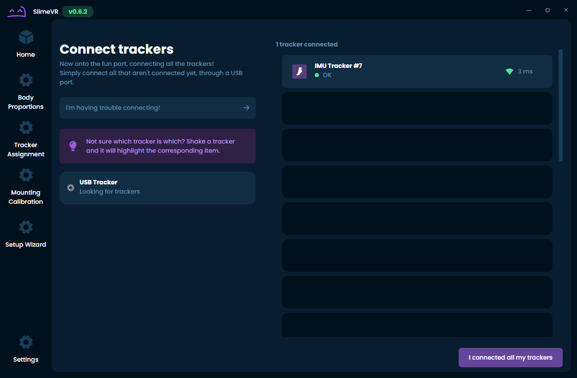
-
Hover over and click on the unassigned tracking points that you want to use. Shaking your tracker will highlight it. Click I Assigned all the trackers once you're done.
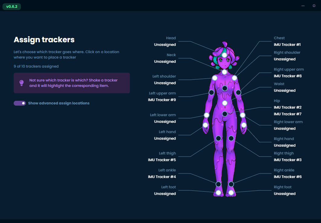
-
Congratulations! You connected all of your trackers, but there's still more left to do. Click I'm ready once you have your trackers on.
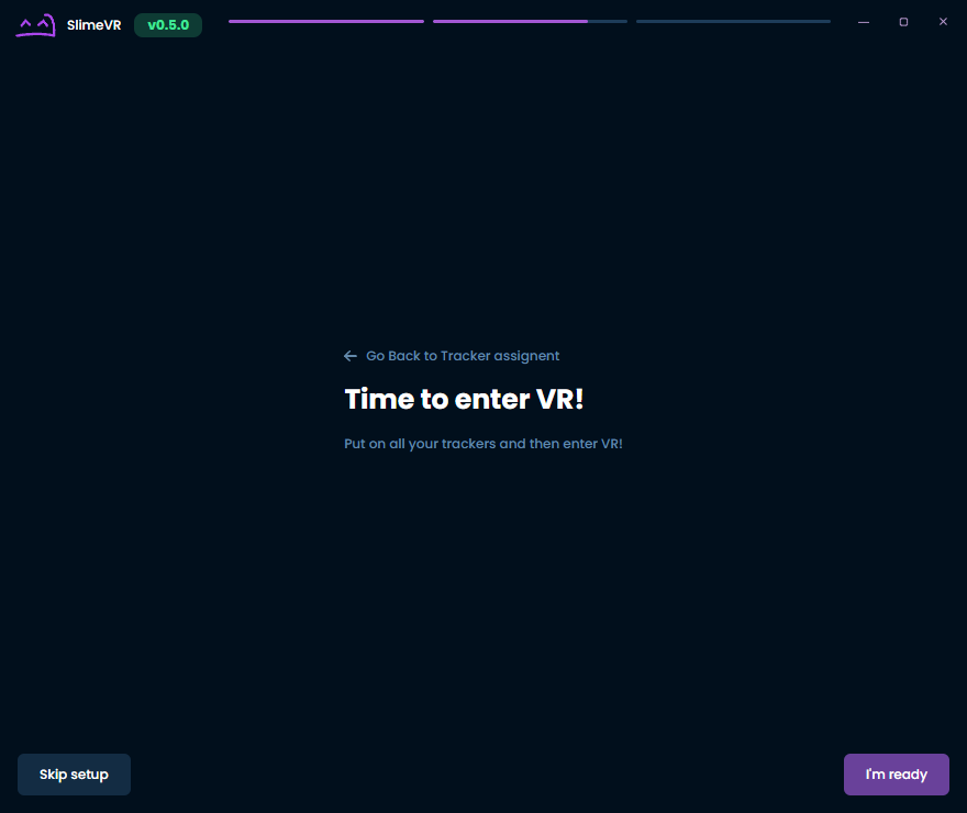
-
This next part is for making sure that your trackers will move in the right direction. Simply follow the instructions shown and then click Next step once your mounting orientations have been calibrated. More information on mounting can be found on the Putting on your trackers page.
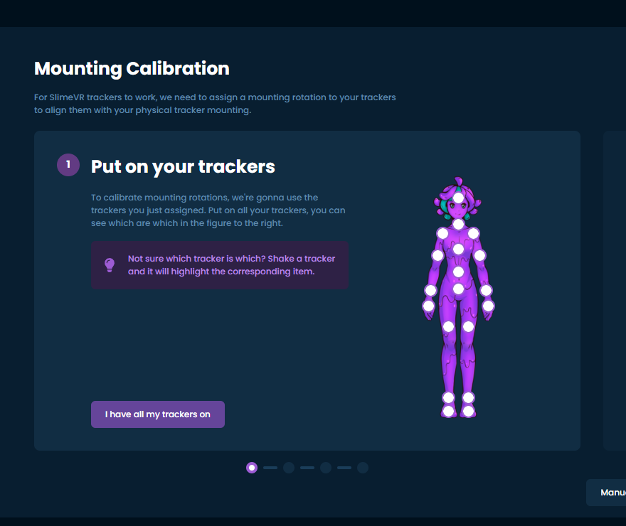
-
At this time, the reset tutorial isn't ready, but you can check the page on reset bindings for more information in the meantime. Simply click Continue.
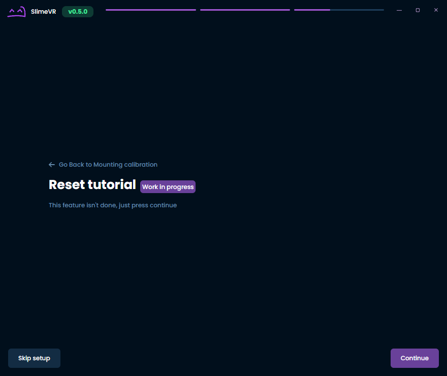
-
You'll want to be in VR for this final step. This involves wiggling around with your feet planted so that your body proportions can be determined. Simply follow the instructions shown. Be sure to verify your results and that nothing is obviously incorrect like having a neck length of 100 cm! Click Continue once you're done.
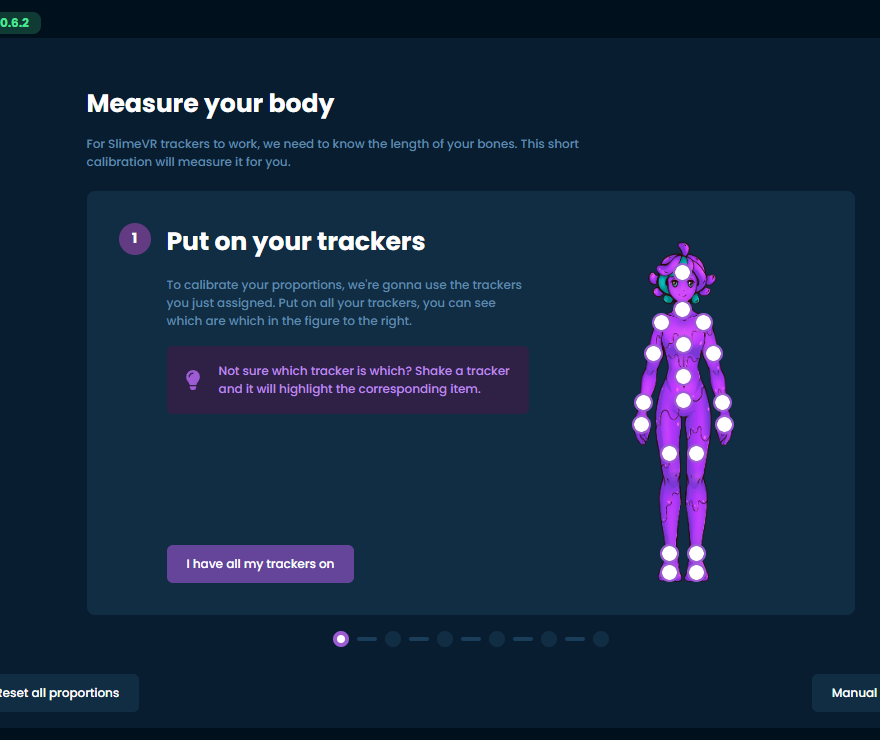
-
You're done! If you've made it through all that, you should be ready to start using SlimeVR!
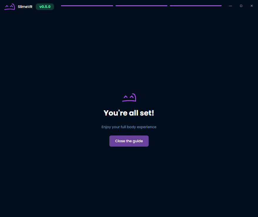
Troubleshooting
If all trackers don't show up, this can be caused by Windows Firewall blocking the connection. To fix this, go to SlimeVR Server folder and run firewall.bat as administrator. There are additional steps that can be taken on the common issues page if this does not work.
For additional information on trackers, you may want to enable Developer mode. The setting for this can be found under Settings, General, and then Interface.
If some trackers don't show up, try turning them off and on again. You can rotate tracker around and see it change rotation in the server to figure out which tracker is which.
If some trackers don't change their rotation as you move them (including extensions), or display 0 0 0 rotation, try turning them off and on again, usually it should fix the issue.
If any tracker displays ERROR as it's status, or have orange and blue light permanently on, that's not good. Try restarting them and see if it helps. If not, contact Eiren.
Created by eiren, edited by adigyran, calliepepper, emojikage and nwbx01, styled by calliepepper.
Configuring Your Trackers
Configuring How Many Virtual Trackers You Need
Before launching SteamVR, check the checkboxes relative to how many SteamVR virtual trackers you wish to spawn.
![]()
Please note that this only affects the virtual trackers in Steam and not your SlimeVR trackers. If you only have Waist and Feet enabled, they will still be accessing up to an 8 IMU setup (waist, chest, upper legs, lower legs and feet). At the moment, VRChat supports 11 virtual trackers, including headset and controllers.
SteamVR Trackers to Enable Depending on Your Set
- 5+0: waist and feet.
- 5+1: chest, waist and feet.
- 5+3: chest, waist, knees, feet.
- 7+3: chest, waist, knees, feet, elbows
Trackers marked in italic should only be enabled if your game or application supports it (VRChat does).
One peculiarity to note is that SlimeVR lower leg and feet trackers will combine into a single SteamVR tracker. Similarly, hip and waist trackers will also combine into a single SteamVR tracker.
Do not enable trackers you do not need as this could lead to in-game calibration issues.
Launch SteamVR when you're ready.
Access the SlimeVR Server in VR
There are several ways you can view and interact with the SlimeVR GUI while in VR. These include using the Steam dashboard (free), Desktop+ (free) OVR Toolkit (paid) or XSOverlay (paid).
Reset Trackers
When getting in VR, your trackers will be floating all over the place and won't be following your body. To fix this, you need to perform a tracker reset.
To Perform a tracker reset:
- Stand straight, legs vertical (not together), trackers facing their designated direction.
- Press the RESET button in the SlimeVR Server.
- Look forward and maintain your pose until the countdown finishes.
- After the timer ends you should see that the trackers point in the right direction and are under you.
Look down. After resetting, the trackers should be directly under you and follow your movement; however as you haven't configured the body proportions yet, they may not be positioned accurately compared to your real body.
See setting a reset keybind for a quick and easy way to reset your trackers while in VR.
Created by eiren, edited by adigyran, calliepepper, smeltie, erimel, emojikage and nwbx01, styled by calliepepper.
Putting on Your Trackers
Put trackers on based on your predefined positions. You can use any comfortable position for you, but there are a few rules:
![]()
- You should set Tracker role to the proper role according to body part you put your tracker on. This includes tracker extensions. Use pictures to reference role names and their recommended mounting points.
- You should set Tracker orientation according to your mounting orientation. When you mount it, make sure they sit tight, and face as much in this orientation as possible when you're standing straight. I.e. "Forward" should face the same way your HMD is facing when you look forward while standing! Alternatively, you can try the automatic mounting calibration.
- You can mount trackers tiled forward/backward or on the side, this will not mess up the tracking.
- You can mount trackers in any place on the designated body part you find comfortable, however the less the area is deformed by muscular movement the better the tracking will be. Make sure the tracker moves when you bend the joint to register movement. Pay special attention to the waist tracker, there are many places where you can mount it and it won't register you bending over. Mount it above your hip, around the level of your belly button.
Recommended Tracker Placement
- 5 trackers: chest, upper legs and lower legs.
- 6 trackers: chest, hip, upper legs and lower legs.
- 7 trackers: chest, waist, hip, upper legs and lower legs.
- 8 trackers: chest, hip, upper legs, lower legs and feet.
- 9 trackers: chest, waist, hip, upper legs, lower legs and feet.
- 10 trackers: chest, hip, upper legs, lower legs, feet and upper arms.
- 11 trackers: chest, waist, hip, upper legs, lower legs, feet and upper arms.
- 12 trackers: upper chest, chest, waist, hip, upper legs, lower legs, feet and upper arms.
- 14 trackers: upper chest, chest, waist, hip, upper legs, lower legs, feet, upper arms and shoulders OR lower arms (for VRChat shoulder-tracking only).
Recommended Mounting Points
- Upper Chest: facing forward, above the breasts.
- Chest: facing forward, on the middle or lower part of the chest.
- Waist: facing foward or to the side on your waist (above you hip, around the level of your belly button) depending on your build.
- Hip: facing forward or back on your hip (where you put your belt).
- Upper leg: just above the knee or higher up the thigh depending on your build.
- Lower leg: on the ankle facing any direction you like.
- Foot: on top of the foot. Trackers 'up' facing toward the ankle, and 'front' facing the ceiling.
- Upper arm: on upper arm (above elbow), on the side or back (forward being your bicep).
- Shoulder: on top of the shoulder.
- Lower arm: on lower arm (below elbow), inwards, close to the elbow.
It is also recommended to mount your trackers directly on bare skin for better adhesion (more stability and less sliding).
Alternative mounting points
Ultimately the perfect mounting positions are dependant on the person, as body shapes differ greatly. Feel free to experiment by changing trackers one at a time to see what difference it makes.
Created by eiren, edited by adigyran, calliepepper, spazzwan, erimel, emojikage and nwbx01, styled by calliepepper. Videos created by zrock35
Body Proportions Configuration
SlimeVR uses a virtual skeleton to compute positions from the data it receives from your trackers. As part of the setup procedure, this skeleton is made using your real-world measurements (in cm) for various body parts in order for SlimeVR to compute its skeleton accurately to your real body. While these values can be input directly into the SlimeVR server, it is recommended you use the AutoBone system. Once you have completed the auto-configuration process, it is also recommended to use the measurements above to confirm the accuracy before finalising the automatic values. There is also an option to visually check within VR, described at the bottom of this page.
Measurements

|
Head ShiftThe head shift value is from your headset to about the middle of your head.Neck LengthThe neck length value is the distance from about the middle of your head to your shoulders.Upper Chest Length (est. 12-20) + Chest length (est. 12-20)The Chest Length is roughly the distance from the end of your neck to the end of your chest. When using a single chest tracker, only the sum of the two values is important. When using two chest trackers, the SteamVR tracker will still be calculated from a single chest tracker, but the rest of the spine will use both.Waist Length (est. 20-35)The Waist Length is the distance from your chest to your hips minus whatever you set for Hip Length. For example, if your chest to hip distance is 30 and your Hip Length is 5 your Waist Length would be 25.Hip Length (est. 2-6)This length is used for calculating hip movement, experiment with it but it should be between 2 and 6.Hips widthThe hips width value is the distance between your femurs.Upper Leg Length (est. 35-60)The Upper Leg Length is from your hip to your knee.Lower Leg Length (est. 45-65)The Lower Leg Length is from the knee to your ankle.Foot LengthThe foot length value is the length of your foot, from your ankle to your toes.Hip offset / Chest offset / Foot shiftThese values offset your real trackers from virtual ones, if your avatar has non-human or unusual proportions. A good example of this would be changing your foot shift for an avatar with digitigrade legs that may have the foot further out or back, or to facilitate calibration depending on the viewpoint of the avatar.This also may be used to compensate for a game's particular expectation for trackers, Increasing the value moves the offset Down(Chest, Hip) or Forward(Foot) Skeleton offsetThe Skeleton offset value offsets all your trackers from their physical position forward (with a positive value) or backwards (with a negative value). This can be left untouched unless you need it. |
AutoBone / Automatic body proportions calibration
AutoBone (also known as "automatic body proportions calibration") removes the need to manually input bone lengths using automatic bone length calculations recorded through user movements. AutoBone is available as "Automatic calibration" under the "Body Proportions" tab of the GUI.
This bypasses the need to manually set the bone lengths, although it is still possible to fine-tune values manually if needed.
How to Use
- Make sure the headset is ON and worn on your head during this process.
- If you use an standalone headset, remember to enable the Guardian/Boundary as SlimeVR can't get your height correctly otherwise.
- During the recording, you must keep your heels in the same position, otherwise the resulting values will be invalid.
Text guide
To use AutoBone, follow these steps:
- Before following any of the instructions below, ensure that:
- You have at least enough trackers to track your feet (generally 5 trackers).
- You have your trackers and headset on and are wearing them.
- Your trackers and headset are connected to the SlimeVR server and are working properly (ex. no stuttering, disconnecting, etc).
- Your headset is reporting positional data to the SlimeVR server (this generally means having SteamVR running and connected to SlimeVR using SlimeVR's SteamVR driver).
- Your trackers and headset are tracking properly within the SlimeVR server (ex. mounting is set correctly and you have performed a full reset, legs move the right direction when kicking, bending over, sitting, etc).
- Optionally reset proportions to set a baseline (this is covered by the height step in the GUI since v0.9.0):
- Navigate to the "Body Proportions" tab and ensure you're on "Automatic calibration" and not "Manual calibration".
- Stand up straight and press the "Reset all proportions" button.
- Follow the steps shown on the GUI.
- Make sure to keep your heels on the ground and in the same position for the duration of the recording.
- Press the "Start Recording" button, the GUI will indicate that the recording has started. The recording will last for approximately 30 seconds.
- Move until the text on the button changes back to "Start Recording", the current best-known movements for calibration are as follows, returning to standing up straight after each step:
- Standing up straight, move your head in a circular motion so that your nose is making a coin sized circle while facing forward.
- Bend your back forwards and squat. While squatting, look to your left, then to your right.
- Lean your upper body to one side, then to the other side.
- Roll your hips in a hip-width circular motion as if you're using a hula hoop.
- If there is time left on the recording, you can repeat these steps until it's finished, or stand and wait.
- When the recording is done, SlimeVR will process the recording. After processing is done, you will be able to see new values for your body proportions reported in cm.
- To use the calculated values, press the "They're correct" button. If the values do not look right, you can try recording again using the "Redo recording" button - the recording will start immediately, so make sure you're ready.
- Be sure to click back to the "Home" tab in SlimeVR server after completing the process to re-enable floor detection and leg tweak enhancements.
Visual reference for movement calibration steps
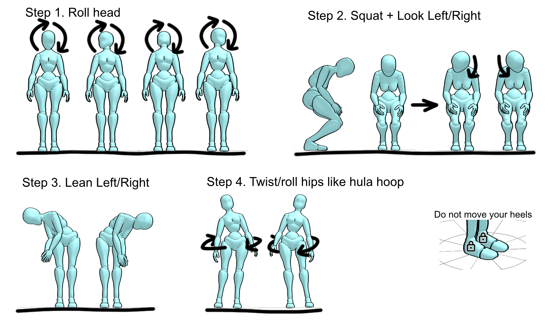
Common Issues / Debugging
If you are having issues with AutoBone:
- Make sure you kept your heels in the same position while recording, don't lift your legs or walk around.
- Make sure your headset isn't lagging, freezing, or teleporting (use the desktop view in SteamVR to start recording rather than Virtual Desktop).
- Double-check that your trackers are mounted correctly and functioning properly.
- Make sure the height in the "Check your height" step of AutoBone is accurate to your own height. It is expected that the HMD height is lower than your real height as it should be around the height of your eyes. The "actual height" reported does not matter and will not affect the process.
- If your actual height is showing an incorrect value, redrawing your Guardian or resetting your playspace floor can often resolve issues.
If none of these help, you can ask for help in the #support-forum or #technical-support channels in the SlimeVR Discord.
To help with debugging in the SlimeVR Discord, you can send a recording while asking for help. A recording includes a recording of all your tracker information to help recreate your setup and will include any movements you do, but no personally identifying information. If you are comfortable with sharing your tracker data, you can find your recordings at "%AppData%\dev.slimevr.SlimeVR\AutoBone Recordings". The most recent recording is auto-saved as "LastABRecording.pfr" and any manually saved recordings will be "ABRecording1.pfr", "ABRecording2.pfr", etc., with the highest number being the most recent.
For more information on how AutoBone functions, check how AutoBone works.
Configuring Body Proportions Manually
All this configuration can be done from the SteamVR dashboard or within VRChat (in front of a mirror). Press the + or - buttons to change lengths, all lengths are in centimeters. Pressing Reset all proportions will change the value to a default based on the HMDs current height. It is recommended to use default proportions until you get used to using Slimes, and for testing purposes.
Make sure you have proper mounting before doing this as it will influence your results.
You can use a mirror in VRChat to see your trackers' positions. However, compare SteamVR tracker position to IRL joint's position, not your VRChat avatar's joints positions.
Alternatively, you can use the SlimeVR Overlay in SteamVR to visualize your bones.
Make sure to adjust the values from the top-down.
Head Shift (8-12)
Shake your head left to right as if you’re disagreeing. Adjust your head offset until any movement is negligible. All trackers should stay in place.
Neck Length (8-14)
Move your head up and down as if you’re nodding OR tilt your head to the left and right like a cute, confused, dog. Adjust your neck length until any movement is negligible. All trackers should stay in place.
Upper Chest Length (12-20) + Chest length (12-20)
Modify value until your SteamVR chest tracker is about at the middle of your spine.
- If you only have a single chest tracker, which of the 2 values you change does not matter, only the sum of them.
- If you have two chest trackers, adjust their ratios after adjusting Hip and Waist Lengths so that your spine is the most stable when moving your chest
Hip Length (2-6)
At first set this between 2 and 6, it may require experimentation and changes based on movement observed once all other values are set. If you increase this value you must decrease the Waist Length value an equal amount.
Waist Length (20-35)
Modify value until your SteamVR waist/hip tracker lines up with your hip bones (you can use your controller to line up your IRL hip and tracker).
Upper Leg Length (35-65)
Modify until your SteamVR knee trackers are at your knee joints.
Lower Leg Length (45-60)
Modify until your SteamVR feet trackers are at the level of your ankles.
Feet (when using feet extensions)
Set “foot length” at 0, change “foot offset” (default -5) until feet trackers are inside your avatar’s ankles during T-Pose calibration, or at the same level horizontally, and set “foot length” back to 5.
Hips width (26-32)
Default value is good. Can try to tweak to make your leg trackers line up when resetting, but do not increase this value with the goal of preventing leg crossing.
Hip Offset and Chest Offset
Keep at 0 unless you have a particular problem with your avatar or application/game.
Skeleton Offset (0)
Keep at 0 unless you have a particular problem with your avatar.
Shoulders distance (4-10) and Shoulders width (30-42)
Set Upper arm length to 0 and adjust the values until the elbow trackers are on your shoulders.
Upper/Lower arm distance (20-35)
Adjust so that the SteamVR tracker is on your elbow.
Controller Distance Z (10-20) and Controller Distance Y (2-8)
Rotate wrist and adjust until elbow tracker has the least amount of sliding.
Elbow offset (0)
Keep at 0 unless you have arm tracking problems using lower + upper arm tracking from controller or an elbow tracker binding to your chest.
How AutoBone works
AutoBone works by recording movement data and simulating that movement rapidly while gradually adjusting the bone lengths. When adjusting bone lengths, the algorithm measures the amount the feet slide to know whether it's achieving a better or worse outcome with each adjustment. By iterating over the data multiple times, the algorithm is able to obtain reasonable bone length values with minimal foot sliding.
The AutoBone algorithm uses hyperparameter optimization to estimate bone length values. First, a defined number of samples of movement data are recorded, then using hyperparameter optimization, the algorithm gradually adjusts the bone lengths to minimize the error of foot sliding. Error is calculated through multiple different methods, but generally it is formulated to retain the headset's reported height, "average" human body proportionality, and reduce the amount that the feet slide during movement.
Almost all of the algorithm's internal values are exposed through the config file. Read the following Configuration documentation section to learn more.
Configuration Documentation
All configuration options should be placed in the vrconfig.yml file and are sub-configs to autoBone, for example:
autoBone:
  numEpochs: 100
  initialAdjustRate: 10.0
  adjustRateDecay: 1.0
| Config Option | Value Type | Default Value | Description |
|---|---|---|---|
cursorIncrement | Integer | 2 | The number of samples to increment the cursor by each step |
minDataDistance | Integer | 1 | The minimum distance between samples to be used while adjusting |
maxDataDistance | Integer | 1 | The maximum distance between samples to be used while adjusting |
numEpochs | Integer | 100 | The number of epochs (full loops) to iterate over the data |
printEveryNumEpochs | Integer | 25 | The number of epochs before the progress is logged |
initialAdjustRate | Float | 10.0 | The factor to adjust the values by each iteration |
adjustRateDecay | Float | 1.0 | The factor to decay the adjust rate by each epoch |
slideErrorFactor | Float | 0.0 | The factor of which the foot slide error is used in the error calculation |
offsetSlideErrorFactor | Float | 2.0 | The factor of which the foot offset error is used in the error calculation (captures sliding) |
footHeightOffsetErrorFactor | Float | 0.0 | The factor of which the foot height (y axis) offset error is used in the error calculation |
bodyProportionErrorFactor | Float | 0.825 | The factor of which the body proportion error is used in the error calculation (based on human averages) |
heightErrorFactor | Float | 0.0 | The factor of which the body height error is used in the error calculation |
positionErrorFactor | Float | 0.0 | The factor of which the absolute position error is used in the error calculation |
positionOffsetErrorFactor | Float | 0.0 | The factor of which the absolute position offset error is used in the error calculation |
calcInitError | Boolean | false | When true, the initial error over the data is reported as epoch 0 |
targetHmdHeight | Float | -1.0 | The head/eye height in meters to use in calculations, this is calculated automatically when negative (set by GUI since v0.9.0) |
targetFullHeight | Float | -1.0 | The full/total height in meters to use in calculations, this is calculated automatically when negative (set by GUI since v0.9.0) |
randomizeFrameOrder | Boolean | true | When true, the frame order will be shuffled for each epoch |
scaleEachStep | Boolean | true | When true, the proportions will be scaled to the target height at the end of each epoch |
sampleCount | Integer | 1500 | The number of pose samples to record |
sampleRateMs | Long Integer | 20 | The millisecond interval between each sample to record |
saveRecordings | Boolean | false | When true, recordings will automatically be saved |
useSkeletonHeight | Boolean | false | When true, the automatic height will be calculated from the current body proportions rather than from the recording |
randSeed | Long Integer | 4 | The seed to use for randomization to make it predictable between runs |
Created by butterscotch.v, eiren and calliepepper, edited and styled by calliepepper, erimel, emojikage, butterscotch.v, zrock35 and spazzwan.
Setting up Reset Bindings
Reset bindings are one of the most essential features to set up for an enhanced experience, allowing you to trigger resets quickly without taking focus away from your game. In this guide, we'll show you how to set them up.
SteamVR binds via bindings provider
To set up reset bindings using the built-in bindings provider, do the following:
- Head over to your SteamVR settings (make sure "Advanced Settings" is enabled).
- Go to Controllers > "Show Binding UI" > "Show More Applications".
- Scroll down and select "SlimeVR-Bindings-Provider".
- Click the plus icon to the right of the button you'd like to use for triggering the reset.
- Select the Button mode.
- Set one of the inputs (Click/Touch, or Long/Held/Touch which are visible after clicking More options) to the reset you'd like to trigger.
All done! You’re now ready to trigger quick yaw resets in-game. You can even bind a reset to a combination of controller buttons in the Chords menu of the bindings editor. Fastest reset in the west.
Keyboard Shortcuts
The SlimeVR Server has the following default key bindings:
CTRL+ALT+SHIFT+Ufor Quick reset.CTRL+ALT+SHIFT+Yfor Reset.CTRL+ALT+SHIFT+Ifor Mounting reset.CTRL+ALT+SHIFT+Ofor Pause tracking.
These keybindings can be configured by editing the following lines of the vrconfig.yml file:
keybindings:
  fullResetBinding: "CTRL+ALT+SHIFT+Y"
  yawResetBinding: "CTRL+ALT+SHIFT+U"
  mountingResetBinding: "CTRL+ALT+SHIFT+I"
  pauseTrackingBinding: "CTRL+ALT+SHIFT+O"
If you want to bind these to your controller, you will need an additional application such as:
- OVR Advanced Settings ($7.99 USD on Steam or free on GitHub)
- OVR Toolkit ($12 USD on Steam)
OVR Advanced Settings Bindings
Make sure OVR Advanced Settings is closed before following these steps or you will encounter problems.
-
In the Windows Explorer window, enter
%appdata%/AdvancedSettings-Team/OVR Advanced Settings.iniin Address bar and press Enter. Notepad with theOVR Advanced Settings.inifile contents should open. -
Find the
keyboardOne,keyboardTwo, andkeyboardThreelines and replace them with the following lines:keyboardOne=^*>y ; CTRL+ALT+SHIFT+Y - Reset keyboardTwo=^*>u ; CTRL+ALT+SHIFT+U - Quick reset keyboardThree=^*>i ; CTRL+ALT+SHIFT+I - Mounting resetNote: If you changed default SlimeVR Server key bindings, refer to Keyboard Input Guide.
-
In SteamVR Dashboard, open OVR Advanced Settings and select Bindings. If you don't see the icon for OVR Advanced Settings on your dashboard, try running OVR Advanced Settings from your Steam library and check if the icon appeared on your dashboard.
-
In the opened window, select the Misc tab.
-
Double-click the plus sign near the desired button name to add a binding.
-
In the opened dialog window, select BUTTON.
-
Click None near the desired button action. To see more button actions, click Show more.
-
In the opened Boolean Actions window, select Keyboard Shortcut One.
-
Repeat previous two steps for Keyboard Shortcut Two and Keyboard Shortcut Three.
OVR Toolkit
If you do not wish to bind keyboard shortcuts directly to your controller buttons, OVR Toolkit's "wristwatch" has Macro functionality that can be used to trigger Resets and Quick Resets.
Demo GIF:
- Open the OVR Toolkit settings, it may be in the system tray.

- Click on "Settings" on the top, then "Setup Wrist Macros" on the right.
- Click on "Macro Icons" at the bottom, this will open a folder that you can place PNGs for custom macro icons. Download and copy these two icon files for the resets into there. Reset Icon. Quick Reset Icon.
- Click "Add Macro", and click "Add key press" until you have enough for each key of the binding. (Default needs 4).
- For each key in sequence, click "Rebind" and then push one of the binding's buttons once. Having the letter as the bottom key is important, as that is the order the keys are pressed. Entering
Y+CTRL+ALT+SHIFTwould not work, butCTRL+ALT+SHIFT+Ywould. - Click the blank icon square on the left side of the entry, and choose the corresponding icon. (To differentiate, Reset is the basic reset symbol. Quick Reset has the flame in the middle.)
- Repeat steps 5-7 for the other binding.
- Click "Save Changes", and then check the Macros tab on your OVR Toolkit wristwatch for your new bindings! (You may need to restart OVR Toolkit!)
Warning
Currently, the SlimeVR server resets the positions the instant the binding is pressed, which is not ideal if you are looking down at your extended arms. However, this can be overcome with a simple AutoHotKey script until a configuration option is added to add a countdown to those bindings. Save this script with a .ahk extension.
If you want this script to also start up with Windows, right click it, Create Shortcut, and copy that shortcut to C:/Users/<YourUsername>/AppData/Roaming/Microsoft/Windows/Start Menu/Programs/Startup
#NoEnv  ; Recommended for performance and compatibility with future AutoHotkey releases.
; #Warn  ; Enable warnings to assist with detecting common errors.
SendMode Input  ; Recommended for new scripts due to its superior speed and reliability.
SetWorkingDir %A_ScriptDir%  ; Ensures a consistent starting directory.

; Reset
$^+!y::
SoundBeep
Sleep 3000
SoundBeep
SoundBeep
SoundBeep
Send, ^!+y
return

; Quick Reset
$^+!u::
SoundBeep
Sleep 3000
SoundBeep
SoundBeep
Send, ^!+u
return

; The beeps are just for extra feedback and can be safely removed.
Notes
- If you reset your playspace (for example long pressing Oculus button on Quest), you will need to do a tracker reset.
- OpenVR Advanced Settings' keybinds may not work well in certain languages. If this is the case for you, start SteamVR with your system's language set to English.
- SlimeVR Server uses Java 17.
- If you need the SlimeVR Steam driver you can find it here.
Created by Eiren, edited by adigyran, calliepepper, smeltie, emojikage and nullstalgia, styled by calliepepper. Videos created by zrock35. OVRT GIFs created by nullstalgia.
OSC (Standalone Tracking)
OSC stands for Open Sound Control. It was originally developed to be used to connect and control music equipment in a simple, open, and standard way. VRChat developed a system for it to be used to control the avatar and virtual trackers, allowing for fully body tracking on any headset that support standalone VRChat. You can read the VRChat documentation on it here.
Compatible headsets
This is the list of headsets that officially support standalone VRChat as of the time of writing this. For a fully up to date list you can check VRChat's official wiki here
- Meta Quest 2
- Meta Quest 3
- Meta Quest 3S
- Meta Quest Pro
- Vive Focus Vision
- Vive XR Elite
- Pico 4
- Pico 4 Pro
- Pico 4 Ultra
OSC Setup
Once you have set up your trackers and mounted them correctly, you can set up OSC. In the SlimeVR Server, navigate to Settings > OSC > VRChat OSC Trackers and enable OSC.
Software directly on quest
If the server is running on the Quest, leave the address as 127.0.0.1.
Software on other device (Phone, laptop, older PC etc)
If the server is not on the Quest, put in your Quest's IP. You can get this by opening the Quick Settings menu on your Quest, selecting Wifi, your currently connected network, and scroll down and click the arrow. The IP address is listed there (video tutorial on how to find your Quest's IP).
Now that you have the SlimeVR side set up, you can now connect VRChat to SlimeVR.
Please perform a full reset now if the app is running on your Quest directly
Open VRChat on your Quest.
Using the Radial Menu, select Options at the top, OSC, and then enable it. You can verify that the trackers are being seen by VRChat by selecting "OSC Debug" if you like.

Walk over to a mirror, open the quick menu, and press "Calibrate FBT". Make a T-Pose, lining yourself up with the T-Pose in the mirror. Press reset on the server (unless you're running it on your Quest). Pull both triggers, and you're done!
Note: If SlimeVR is running on your Quest and the trackers are initially misaligned, you can navigate to the IK settings in VRChat's quick menu and press "Auto-Center OSC Trackers" once or twice.
Created by lordbagel42, Smeltie. SlimeVR OSC implementation by erimel.
IMU Calibration
Make sure that when you turn on your tracker it's lying on a flat surface. The sensors need to calibrate for 20-30 seconds in a stable environment. This should be done every time you turn on your trackers, failing to do so will result in an increased rate of drift.
Some IMUs, such as the BNO085 or ICM20948 do not require any specific manual calibration and can be used immediately after letting them rest.
Every other IMU will need to be calibrated in order for it to work properly. This calibration only needs to be done once. You can only calibrate one IMU at a time, so if you have any extensions, they will also need to be calibrated. Please note that when using extensions, calibration data is saved onto the main tracker, so swapping extensions between main trackers will require recalibration.
BMI160 with firmware v0.3.2 and below, MPU9250, or MPU+QMC5883L
- Plug in your microcontroller (D1 Mini, NodeMCU, or other)
- Open the SlimeVR server, and click Settings, and then click Serial Console under Utilities.
- Flip the IMU you want to calibrate upside down and press the reset button on your microcontroller or the reboot button in the SlimeVR server. You should see a message indicating that you need to flip the IMU right side up to begin calibration.
- Upon flipping the IMU over, calibration should begin. To successfully calibrate your IMU you need to gently rotate the IMU in all 3 axes.
- After approximately 60 seconds has passed, the tracker should be successfully calibrated and will begin to show rotation in the SlimeVR server.
BMI160 with firmware v0.3.3 and above, BMI270, LSM6DSO and LSM6DSV or other sfusion IMUs
If you have a BMI160 and firmware v0.3.3 or higher, or you are using BMI270, LSM6DSO, LSM6DSV or other sfusion IMUs you will need to calibrate your IMU in a different way, unless specified otherwise in the firmware:
- To get the best possible calibration, it is advisable to heat your trackers to their normal operating temperature. To do this, put on your trackers for at least 20 minutes before starting calibration.
- To get additional feedback on the calibration process, you can connect to the serial console. This is entirely optional.
- Plug in your microcontroller (D1 Mini, NodeMCU, or other)
- Open the SlimeVR server, and click Settings, and then click Serial Console under Utilities.
- Flip the IMU you want to calibrate upside down and press the reset button on your microcontroller or the reboot button in the SlimeVR server. You should see a message indicating that you need to flip the IMU right side up to begin calibration.
- Upon flipping the IMU over, calibration should begin. Leave the IMU still for at least 15 seconds.
- Now, set the IMU on a flat surface on each of the remaining 5 sides, waiting until the serial console or led indicates that you can change position for each side.
- The IMU should now be calibrated and will begin to show rotation in the SlimeVR server.
BMI160 temperature calibration (tcal)
Optionally, you can perform temperature calibration for BMI160 IMUs, which is a more advanced process but significantly reduces drift:
With a 3d printer
- Place your trackers in a fridge or freezer for a period of time to cool them down to below 15°C. If you're unsure about the temperature of your trackers, you can check it in the SlimeVR Server when the tracker is turned on.
- Turn on your trackers and gradually heat them, calibration will automatically begin if the temperature is below 15°C.
- You can use something like a 3D printer bed or a heat gun, but be careful not to overheat your battery or melt your case.
- It is important to not rush this. Temperature calibration should take at least 15 minutes, otherwise you risk having a partial calibration, which can lead to increased drift.
- The calibration will be complete and automatically saved once the IMU reaches 45°C.
With a hairdryer
- Place your tracker in a fridge or freezer for a short period of time (about 10 minutes) to cool it down to below 15°C.
- Take the tracker out and put it on a stable surface like a table.
- Open the SlimeVR app -> Turn on developer mode -> On the home page at the bottom-right, toggle "More info" to see all details about your Slime and it's temperature.
- Turn it on and let it sit until it reaches operating temperatures naturally; Don't use a hairdryer yet! When you put your tracker closer to your computer you can reach a higher temperature quicker.
- Wait until your tracker's temperature levels out. Warm it up with your hairdryer to around 43°C, do not reach 45°C yet.
- Let it cool down naturally to operating temperature again.
- Once around 30°C, use the hairdryer to get it to around 46°C to finish measuring the last points for your TCAL, then let it cool down.
- Check if you did well with the USB WebUI checking tool
The tracker can be moved around during temperature calibration, but it will not record any data while it's in motion.
It may be difficult to determine how the calibration process is going. Setting #define BMI160_TEMPCAL_DEBUG to true in the defines_bmi160.h file in the firmware exposes more information about the process, replacing the regular temperature readout with temperature calibration debug info in the SlimeVR Server.
The format is AXXYY, where A is calibration status (1 - not in calibration mode, 2 - calibration in progress), XX represents calibration progress from 0 to 60, and YY is the temperature. A fully temperature calibrated tracker would show up as 160YY.
Alternative Wi-Fi Options
Windows Mobile Hotspot
You can set up a Wi-Fi hotspot through Windows using the Mobile Hotspot feature.
- Navigate in Windows settings to Settings > Network & internet > Mobile hotspot.
- Under the "Properties" section, click Edit and set the name and password to whatever you want.
- Ensure that the "Band" (aka "Network band") is set to 2.4 GHz for SlimeVR trackers. The hotspot can only be 2.4 GHz or 5 GHz and not both, so if it's set to "Any" or 5 GHz, then it will not support 2.4 GHz.
- Once you have configured the network, you can toggle the "Mobile hotspot" on.
Recommended Routers
WiFi based SlimeVR trackers have known issues with Dormitory/College and ISP/Network provider based WiFi networks. In these cases it is recommended to purchase a secondary router to use with SlimeVR trackers.
These Gl.iNet routers are commonly used and tested by the SlimeVR community. These specific models have been tested and are widely used by the community:
SlimeVR Tracker capability only:
- $34.9 USD Gl.iNet Opal.
SlimeVR Tracker and Wireless Virtual Desktop/Steam Link capable:
- $92 USD Gl.iNet Beryl.
- $155 USD Gl.iNet Slate 7.
SlimeVR Tracker, Wireless Virtual Desktop, and general home internet capable:
- $159 USD Gl.iNet Flint 2. Dual band.
- $199 USD Gl.iNet Flint 3 Tri band. Needs line of sight to effectively use the 6GHz band for wireless VR.
- $169 USD Gl.iNet Flint 3e. Dual band version of the Gl.iNet Flint 3. Recommended if you don't need the 6GHz capability of the original Flint 3.
Page updated with recommendations by Amebun. If you have router suggestions or more information, use the documentation channel on the Discord.
Applications and Variants
Thanks to the amazing SlimeVR community, we are proud to show you some of the great tools they have made! You can find more information on owoTrack, SlimeTora and L,i,me down below.
- owoTrack App
- SlimeVR Wrangler
- SlimeTora (HaritoraX)
- SlimeVR on Linux
- Termux Setup
- L,i,me-Slimes
- ShadowPC with SlimeVR
- Using SteamVR trackers (Vive/Tundra) along with SlimeVR
- VRChat Configuration
- Mobile Setup
- MacOS Installation
owoTrack App
owoTrack is a mobile application that can be used for VR tracking using your phone. The application uses SlimeVR Server for tracking. To set up SlimeVR Server, refer to SlimeVR setup guide.
If you're using trackers/phones with owoTrack app for tracking, there is minimum amount of 5 trackers/phones for full body tracking. One phone can be used if you want only waist tracking. Waist tracking can also work with owoTrack SteamVR driver, without SlimeVR.
Your PC and trackers/phones should connected to the same local network.
Table of Contents
- Download Links
- FAQ
- How many trackers or phones do I need to use for leg tracking?
- I heard I could use 3 phones for leg tracking
- I have only one/two phones
- I try to run SlimeVR but nothing happens. Why?
- My trackers are connected to the SlimeVR Server, but they are not moving in SteamVR
- My controller is a tracker. How do I fix this?
- In what order should I start SteamVR and SlimeVR Server?
- My phone isn't connecting to the server
- I have an iPhone and it disconnects after 10 minutes
- Virtual trackers on SteamVR are grayed out
- Other issues
Download Links
Android build available on Google Play: https://play.google.com/store/apps/details?id=org.ovrgyrotrackersync
IOS build available on the App Store: https://apps.apple.com/au/app/owotrack/id1563711037
Created by ferdimarti#2111
FAQ
How many trackers or phones do I need to use for leg tracking?
You need at least 5 trackers or phones for FBT using SlimeVR.
I heard I could use 3 phones for leg tracking
You can't. You will have a bad time, and that's not our fault. Your knees won't bend and it's an overall worst experience. Required minimum is 5.
I have only one/two phones
You can use the official owoTrack driver for waist or SlimeVR Server for waist (+ chest if you have 2 phones). This will not track your legs.
I try to run SlimeVR but nothing happens. Why?
Refer to the SlimeVR setup guide for how to set up SlimeVR.
My trackers are connected to the SlimeVR Server, but they are not moving in SteamVR
Make sure you have the correct roles selected in the SlimeVR Server for your trackers/phones. They should be Waist, Left Uppper Leg, Right Uppper Leg, Left Lower Leg and Right Lower Leg.
To learn how to set up tracker roles, refer to SlimeVR setup guide.
My controller is a tracker. How do I fix this?
You need to assign roles to your trackers in SteamVR:
- In SteamVR, go to Settings > Devices > Manage Trackers.
- In the tracker list, find the ones named
/devices/SlimeVR/SlimeVRTracker#and give them the roles WAIST, LEFT_FOOT, RIGHT_FOOT from top to bottom. - Restart SteamVR.
To learn how to set up tracker roles, refer to SlimeVR setup guide.
In what order should I start SteamVR and SlimeVR Server?
The order does not matter.
My phone isn't connecting to the server
Check that the IP is correct.
You can input 255.255.255.255 as IP to owoTrack Android app
To check your IP address, you can open the PowerShell window or Command Prompt window (cmd.exe) and execute ipconfig command and get your PC IPv4 address field - for example 192.168.1.2 and put it in owoTrack app.
If you're using an iPhone, check that OwOTrack can communicate with devices on your local network. You can find this in Settings > Privacy > Local Network, ensure that the toggle next to OwOTrack is on.
I have an iPhone and it disconnects after 10 minutes
Apple has restrictions on apps for networking in background. The workaround for this is currently being investigated.
To workaround this:
- Enable Guided Access. You can find this setting in Settings > Accessibility > Guided Access.
- Disable screen auto-lock. To do this, go to Settings > Display & Brightness, tap Auto-Lock and set it to Never.
- Start owoTrack app.
- Turn down the screen brightness completely to save battery.
Virtual trackers on SteamVR are grayed out
This is expected behavior, check if trackers present in VR.
Other issues
You may also need to set correct firewall settings for owoTrack to work correctly. Download firewall.bat, move it to a directory without spaces or symbols in its name and run the bat file as administrator.
Created by adigyran with help of mightygood, edited and styled by calliepepper and emojikage
SlimeVR Wrangler
This guide will help you install and use SlimeVR Wrangler, which allows the use of Nintendo Switch Joycons as SlimeVR trackers.
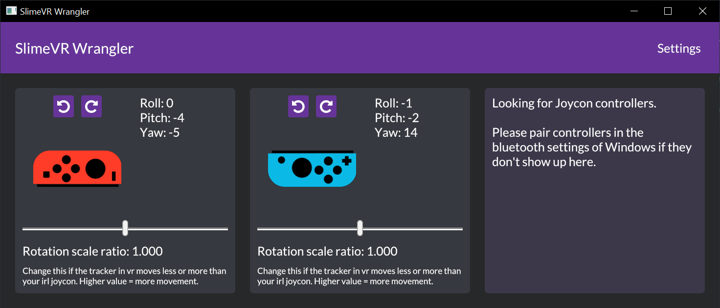
Setup
You need bluetooth on your computer.
- Download and set up SlimeVR
- Download SlimeVR Wrangler
- Start both the SlimeVR server and SlimeVR Wrangler
- Connect your Joy-Con trackers to the computer (Guide for Windows)
- Make sure the SlimeVR Server is running, then press "Search for Joycons" inside SlimeVR Wrangler
- The Joy-Con should show up in the window!
- Set up the new tracker in the SlimeVR Server
Mounting
Keep the joystick pointed outwards, it should not poke into your skin.
After connecting the Joy-Con's in the program, rotate them in the program to be the same rotation as they are if you are standing up.
Attach the Joy-Con's in the direction that works best for you, refer to the page on putting on your trackers for mounting position and tracker assignment.
Issues
Many! This is an alpha version, and there's no guarantees about anything.
- Rotation tracking is bad! - Yup, sorry. In the future there will be settings to help fine tune the tracking. It's recommended to set a keybinding to reset.
- It stops tracking when I turn around! - Bluetooth does not have a good range, you might have better luck with a different bluetooth adapter.
- Probably more.
My Joy-Con's are connected in the Windows bluetooth menu but won't show up!
This is a problem that might be related to a newer Windows update. Try this, and it might fix it:
- Go to the Windows Setting app -> Bluetooth & other devices.
- Press on the Joy-Con that won't connect. Press "Remove device".
- Pair the device again. It should now show up.
Created by Carl (https://github.com/carl-anders), edited by nwbx01
SlimeTora
SlimeTora is a program that connects the HaritoraX trackers to the SlimeVR server so you can use them as SlimeVR trackers, coming with additional features such as per-tracker settings. It supports the HaritoraX Wireless and HaritoraX Wired (1.1b/1.1/1.0) models.
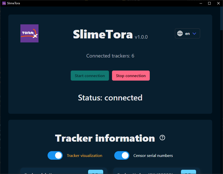
Prerequisites
- A PC and VR headset capable of running/streaming SteamVR (Windows/Linux)
- Optionally, you can instead use OSC in SlimeVR to forward the data to a standalone HMD (e.g. Quest, Pico, etc).
- A supported set of HaritoraX trackers (see this for the supported models)
- Latest version of SlimeTora
- Latest version of SlimeVR server
- New to SlimeVR and SlimeVR server? Read the SlimeVR basics wiki page here.
- Latest version of HaritoraConfigurator
- The trackers must be paired/connected via the software at least once (and to make sure connections are working).
Setup
More details on setting up the software can be found on SlimeTora's
Getting Startedwiki page: https://github.com/OCSYT/SlimeTora/wiki/Getting-Started
SlimeTora setup
- Download the latest release of the app in SlimeTora's releases page.
- Extract the zip archive into its own folder and run the program (
SlimeTora[.exe]).- On Linux, make sure to mark the binary as executable:
chmod +x ./SlimeTora
- On Linux, make sure to mark the binary as executable:
- The "onboarding" screen will appear. Choose how you want to set up SlimeTora, automatic or manual.
- Automatic setup is recommended and will guide you through the setup process in-app. You may skip the following instructions and focus on the app's instructions instead.
- If you would like to set it up manually (or automatic setup does not work for whatever reason), read on.
- Press "Manual setup (skip)" and scroll down to "Program settings":
- Select the model of HaritoraX trackers you have under "Tracker model" (
HaritoraX Wireless/HaritoraX 1.1b/1.1/1.0). - Select the supported connection mode you want to use to connect to your trackers (
Bluetooth/COM / GX(6/2)).- These two modes can also be used at the same time if on
HaritoraX Wireless.
- These two modes can also be used at the same time if on
- (
COM/HaritoraX 1.1b/1.1/1.0) Select the COM port your bluetooth adapter has assigned the trackers to.- The port for the
HaritoraX 1.1b/1.1/1.0(wired) trackers can be found in HaritoraConfigurator's "communication settings".
- The port for the
- (
COM/GX(6/2)/HaritoraX Wireless) Select up to 4 COM ports that your trackers are on (3 if only using GX6, 4 if using GX6+GX2).- Usually, this is the first four (consecutive) available ports. Some COM ports (e.g.
COM1) are usually already used by other devices like your motherboard, so the ports are likelyCOM2,COM3,COM4(andCOM5for GX2). - Check
Device Managerto see what ports are being used by the trackers asUSB Serial Devices.
- Usually, this is the first four (consecutive) available ports. Some COM ports (e.g.
- Select the model of HaritoraX trackers you have under "Tracker model" (
- Change the program's settings to your liking (see this for explanations).
- Continue to SlimeVR setup.
SlimeVR setup
- Install and run SlimeVR server, turn on your trackers, and press
Start connectionin SlimeTora. - If running SlimeVR server for the first time, go through the initial setup:
- Accept all popups that mention a "new tracker" was detected at any point during the setup (these are your trackers!)
- Skip the
Input Wi-Fi credentialsscreen by pressingSkip Wi-Fi settings. - Press
I put stickers and straps!. - Assign the trackers to your body (shake to identify the trackers, or physically double tap them).
- Perform
Automatic Mountingto calibrate the mounting positions.- Manual mounting seems to be quite finicky and you may need to mess with it to get it right (which is why automatic is recommended)
- Choose a proportion calibration method (automatic/manual).
- If this isn't your first time (or skipped initial setup):
- Accept all popups that mention a "new tracker" was detected (these are your trackers!)
- Assign the trackers to your body (shake to identify the trackers, or physically double tap them) in
Tracker Assignment. - Perform an
Automatic Mountingcalibration or amounting reset(you should be in the ski pose).
- Check out the rest of SlimeVR and its settings, and you're done!
Troubleshooting & FAQ
For the full troubleshooting and FAQ pages, check out the SlimeTora wiki: https://github.com/OCSYT/SlimeTora/wiki
I'm stuck on "searching" forever!
If on the HaritoraX Wired or HaritoraX Wireless with any of the GX(6/2) dongles, make sure the correct COM ports have been selected (refer to this). Also, HaritoraConfigurator should be closed; both SlimeTora and HaritoraConfigurator should not be open at the same time as more than one app cannot communicate with a COM port at a time.
If you are using the HaritoraX Wireless with any of the GX(6/2) dongles and you don't have all your trackers connected, you may experience a ~5 second delay before the program actually finds your trackers (instead of being instant) from v1.2.0 and upwards. This is due to backend changes with haritorax-interpreter, it should eventually connect to your trackers however it may or may not be buggy. It is highly recommended you turn on all your trackers before starting a connection - this logic will be redone at some point to prevent this.
Some of my trackers aren't connecting to SlimeTora!
The most common fix for this is to open the HaritoraConfigurator software and make sure they are paired/can connect to the trackers before connecting via SlimeTora again. Unsure why this happens, but this is the most likely fix for you (other than the general checklist) - this especially applies for HaritoraX Wireless users using any of the GX(6/2) dongles.
If you are using Bluetooth (Classic/LE), the trackers have a pretty large delay when you stop the connection on SlimeTora. This is especially noticeable when you restart the connection quickly as the trackers will have not fully disconnected yet. Make sure to wait at least 10 seconds before attempting a reconnection, or wait until the tracker LEDs indicate it has disconnected (slow blinking).
My legs (or other parts) are going backwards!
Double check your tracker assignments and make sure you have done Automatic mounting calibration in SlimeVR server - you may want to attempt it multiple times if the first doesn't work. Manual mounting calibration seems to be a bit finicky with the trackers and may need some messing with to get right.
My full body tracking is off!
The most likely cause for this is an incorrect calibration - try to redo the calibration steps in SlimeVR to improve the results. The following video by ZRock35 is a great guide on how to get the best results for SlimeVR calibration: https://www.youtube.com/watch?v=SYqfQdVseF4
By default, SlimeVR uses the prediction filtering setting to estimate where your trackers will be, so switching from it to smoothing or no filtering may also help with the trackers being out-of-place (unconfirmed).
If you are experiencing issues specifically with lower-body, it is still usually a calibration issue so as mentioned above, try to redo the calibration. You may also try disabling the knees in SlimeVR's settings under SteamVR Trackers to see if it helps (disable Automatic tracker assignment then disabling both knees). The knee trackers will still be used for the skeletal tracking in SlimeVR but not appear as extra trackers in SteamVR, which may help with some tracking issues in your lower-body.
My trackers are not aligned correctly to my body!
Make sure you've done the Body proportions calibration correctly, either manually or automatically, and also make sure you have done Automatic mounting calibration (as manual mounting is quite finicky with these trackers). You can also change settings in the game you are running (e.g. VRChat's IK settings like Legacy calibration) or change the positions of the trackers physically.
If running VRChat, there are some recommended settings for it here.
"Automatic proportions" is disabled/trackers won't show up in SteamVR!
Assuming of course you have your VR headset on at this stage, make sure the SlimeVR add-on in SteamVR has been installed/enabled correctly. You can check this by looking for slimevr in SteamVR settings > Manage Add-ons and enable if it disabled. If it is not installed correctly and isn't showing up, try reinstalling the SlimeVR server.
You may also install the SlimeVR add-on manually by downloading the latest release of the driver, then copying the slimevr folder from the archive into C:\Program Files (x86)\Steam\steamapps\common\SteamVR\drivers\ for Windows or ~/.steam/root/steamapps/common/SteamVR/drivers/ for Linux (create the slimevr directory if it doesn't exist).
Written by JovannMC, software developed by BracketProto & JovannMC
Installing OpenVR Plugin
In order for SlimeVR to communicate with SteamVR, you'll need to install the OpenVR driver into your Steam installation. On Windows, this happens automatically with SlimeVR's installer. On Linux, this needs to be done manually.
If you don't plan to use SlimeVR with SteamVR, this section can be skipped.
1. Download
The latest OpenVR plugin can be downloaded here, or obtained by downloading slimevr-openvr-driver-x64-linux.zip from the latest SlimeVR-OpenVR-Driver release.
2. Identify target directory
You'll then need to identify the root directory of the Steam installation on your system. In most cases, it should be located at ~/.steam/steam/.
3. Extract and install
Extract the archive you downloaded in step 1. This will give you a set of files and folders inside a root slimevr folder.
Then run <steam path>/steamapps/common/SteamVR/bin/vrpathreg.sh adddriver path/to/slimevr, replacing <steam path> with the path to your Steam installation and /path/to/slimevr with the full path to the extracted slimevr folder.
You will need to restart SteamVR for changes to take effect, though you likely won't notice any difference until you have SlimeVR trackers set up.
4. Set the SteamVR launch argument
SteamVR needs a launch argument to allow the SlimeVR driver to connect to the server.
To set the launch argument, open Steam, right-click on SteamVR in your library, select "Properties" and you should see a field where you can enter launch arguments.
In most cases, the launch argument should be: PRESSURE_VESSEL_FILESYSTEMS_RW="$XDG_RUNTIME_DIR/SlimeVRDriver" %command%. You may need to adjust this if you already have other launch arguments set.
Installing Java
The SlimeVR Server depends on Java 17, so you'll need to install it on your system in a way that SlimeVR can access.
Option 1: Install Java globally
The simplest and most straightforward way to set up Java is to install it through your distro's package manager. The specific package name will vary distro to distro, but it will most likely be listed as "openjdk", and you'll most likely want the jre (though jdk will work fine).
Ubuntu:
sudo apt install openjdk-17-jre
Arch Linux:
sudo pacman -S jre17-openjdk
Once installed, the SlimeVR AppImage should automatically detect and use this version of Java to run the internal server.
Option 2: Portable Java
An alternative method to installing Java globally is to download and extract a portable version of the Java runtime.
1. Download Java 17 JRE archive
You can press this button to download the latest Adoptium JRE archive directly:
Or you can download it yourself from the releases page here:
https://adoptium.net/temurin/releases/?version=17
2. Extract and rename
- Extract the downloaded archive (ex.
OpenJDK17U-jre_x64_linux_hotspot_17.0.5_8.tar.gz) to get a folder named something likejdk-17.0.5+8-jre. - Rename the extracted folder (ex.
jdk-17.0.5+8-jre) tojre, such that the directory structure looks something like/jre/bin/java.
3. Bundle with SlimeVR
In order for SlimeVR to locate the portable version of Java, you will need to include it in the same directory as the AppImage. When using the all-in-one AppImage under the "Running SlimeVR" section of this guide, your folder structure should look like so:
Parent Directory
    |- /jre/bin/java
    |- /SlimeVR-amd64.appimage
Running SlimeVR
The recommended way to run SlimeVR on Linux (in a desktop environment) is to use the package built for your distribution. This comes with the server, GUI, and udev rules (required for the serial console) all bundled into one. Config and logs will be stored in ~/.config/dev.slimevr.SlimeVR/.
Arch Linux
Install slimevr-beta-bin from the AUR.
Fedora
Install the .rpm package from the latest server release on GitHub.
Debian/Ubuntu/Mint
Install the .deb package from the latest server release on GitHub.
NixOS
Add the slimevr package to environment.systemPackages in your system configuration.
AppImage (for other distributions)
The latest AppImage can be downloaded from the GitHub releases. The package built for your distribution should be preferred if available, since the AppImage does not include the udev rules. You should then be able to start SlimeVR by simply executing the AppImage.
Serial Console
If you are not using a distribution package of SlimeVR, you will need to grant your user account access to PlatformIO devices. Without the correct access, the Serial Console will continue to display "Connection to serial lost, Reconnecting..." after a SlimeVR tracker has been connected via USB.
The recommended way to gain access is by installing PlatformIO's udev rules. This can be done using the instructions on this page: https://docs.platformio.org/en/latest/core/installation/udev-rules.html
Firewall Rules
On Linux, SlimeVR does not automatically add any firewall rules. If you have a firewall installed, you will need to add the rules manually yourself.
You will need to open ports on:
35903/udp6969/udp21110/tcp8266/udp
Source: firewall.bat
Legacy Setup
If the above installation methods work for you, then you can disregard everything in this section.
If for some reason the above setup does not work for you, then you may need to retrieve and run the SlimeVR components manually.
SlimeVR Server
You can download the latest required slimevr.jar file from this link:
https://github.com/SlimeVR/SlimeVR-Server/releases/latest/download/slimevr.jar
SlimeVR GUI
You can download the latest required GUI from here:
1. Open the latest workflow run
Click on the title of the latest workflow run, this is simply an example; the exact one at the top will change.
2. Download the desired artifact
Once you have the workflow run open, you can find a list of built artifacts. The simplest to use is the AppImage build since it includes all required dependencies and can be run very easily.
You must be logged into a GitHub account in order to download build artifacts.
3. Extract the GUI AppImage/Deb
Once you have the file downloaded (ex. SlimeVR-GUI-AppImage.zip), extract it to get a file like slimevr-ui_0.0.0_amd64.AppImage.
Setting up the install folder
To most easily use the program, you'll need to have things structured in a specific way.
- Make a new folder to contain your installation, name it whatever you want (ex.
SlimeVR Server). - Place the SlimeVR Server, SlimeVR GUI, and optional Java JRE components you downloaded into the folder you made.
Example of the final directory structure:
/SlimeVR Server/
    |- /jre/bin/java  (if using portable Java)
    |- /slimevr.jar
    |- /slimevr-ui_0.0.0_amd64.AppImage
Running the program
Once everything is all set up, all you need to do to run it is execute the AppImage and it should run everything else on its own.
Note: Only tested on Debian and Ubuntu, if you use Arch please ping lordbagel42 in the SlimeVR Discord server.
Created by butterscotch.v
Termux Setup
This guide is no longer recommended. Please see Mobile Setup for an updated method of running SlimeVR on standalone.
This guide will help you install Termux, a Linux "emulator" for Android to use for SlimeVR. The Quest 2 happens to run Android, so you can run the SlimeVR server on it using Termux.
Note: Joycons still require a PC for now and SlimeVR Wrangler.
INSTALLATION - QUEST 2
-
Download Termux (Quest 1/2 is arm64) from here: https://github.com/termux/termux-app/releases
-
Install the .APK file using either Sidequest, ADB, or an already installed file explorer.
-
Open Termux, and run the following command:
bash <(curl https://raw.githubusercontent.com/SlimeVR/SlimeVR-Termux-Installer/main/install.sh)
- Go to https://slimevr-gui.bscotch.ca/ on the device with the server if it doesn't auto open.
If you want to start the server again after closing, DO NOT run the setup commands again. Run:
./start.sh
INSTALLATION - ANDROID PHONES
-
Enable developer mode on your phone. You can do this by opening settings, going to about phone, and finding the "Build Number" and tapping it seven times.
-
Download Termux (most phones are arm64, you can google what yours is) from here: https://github.com/termux/termux-app/releases DO NOT INSTALL FROM GOOGLE PLAY.
-
Click the APK, and allow it to be installed.
-
Open Termux, and run the following command:
bash <(curl https://raw.githubusercontent.com/SlimeVR/SlimeVR-Termux-Installer/main/install.sh)
- Go to https://slimevr-gui.bscotch.ca/ on the device with the server if it doesn't auto open.
If you want to start the server again after closing, DO NOT run the setup commands again. Run:
./start.sh
Updating
On both Android and Quest, to update, all you need to do is start it, it automatically checks for update.
Remote GUI Access
The first step is enabling this on whatever browser you use: https://www.damirscorner.com/blog/posts/20210528-AllowingInsecureWebsocketConnections.html Enable it for https://slimevr-gui.bscotch.ca/ Now that you have done this, you can go to https://slimevr-gui.bscotch.ca/?ip=[QUEST OR PHONE IP]&port=21110 and access the site. Substitute [QUEST OR PHONE IP] with your Quest's or phone's IP address, without the brackets.
Credit goes to butterscotch.v for making all of this work, and lordbagel42 for the documentation, idea, and motivation.
L,i,me-Slimes
Link to current BETA
https://discord.com/channels/817184208525983775/932241053375938562/1116357263758729256
Schematics are the same though

L,i,me by rosdayle
L,i,me is a case and hardware variant of the standard slime aimed to natively support a full 9 IMU setup (with work currently be done on an optional addon to allow 4 more IMUs) while being as streamlined as possible with no degredation to performance.
Who is this for?
- L,i,me is for those who wish to streamline their current standard slime setup by easily converting into a L,i,me.
- For those who want to make a full no compromise 9 IMU setup from the start (with the option to add an extra 4 more IMUs for shoulder and elbow tracking).
- People on a tight budget but want a performant full 9 IMU setup (with the option to add shoulder and elbow tracking in the future).
- Those who intend to use slimevr for mocap and vtubing.
Why choose L,i,me?
- Unlike the standard set up that is limited to 2 IMUs per tracker, each L,i,me tracker supports 4 IMUs (without any software modification). Due to this you only need to make 3 L,i,me trackers instead of 6 typical slime trackers for a full 9 IMU setup.
- Less parts required, making L,i,me the cheapest full 9 IMU setup (as well as 11 or 13 IMU setup with an optional addon).
- Aimed at providing the best stable tracking with comfort and full maneuverability due to being less bulky overall (less main trackers).
- Only need to charge and maintain 3 trackers (4 if you include the optional addon).
- Modular and customisable.
Ongoing support.I can provide any missing models no problem if you message me. However active development has now ended. I will be refreshing and improving upon this eventually in the future under the minted name. However this build is still perfectly functional. You can check out my latest Non-variant release https://www.thingiverse.com/thing:5815469
Doing more with less
- Fewer trackers.
- Fewer parts.
- Lower costs.
- Less building.
- Less maintaining.
- Less units to charge.
- More SLIME!
Github and download link
You can access more information and get the latest L,i,me updates on the Github repo.
FAQ
Can I use this with other standard slime trackers?
Yes, there should be no conflicts with any combinations.
This is my first time soldering or doing DIY with electronics, is this ok for me to build?
If you have confidence that you can or are happy to learn to splice cables cables together, you should be good. While cable splicing is the toughest part of Slime trackers, you will be required to do more of it when constructing a L,i,me.
Can I convert my current standard DIY slimes into L,i,mes
Yes, the original build was made through this process. You will likely need to change the battery and switch though
I don't have enough IMUs can I add them later?
Yes you can in fact start off at minimum 6 IMUs and add the other IMUs later. Please be sure to plan ahead.
When will the elbow and shoulder tracking addon be available?
Shoulder and elbow tracking is available with the double decker addon. Though I personally recommend only using it to track elbows. Unless you have a way to mount shoulder trackers. It would be best to create 2 standard DIY trackers for elbow tracking
Is Neck or Head tracking available?
While I don't openly include it in the count, Neck "or" Head tracking is possible. However I do not recommend neck tracking due to discomfort, possible reduction of accuracy and risk to user. I can however say you can track your head with an extension from the chest unit.
I want to track my entire arm for vtubing or mocap
You can try make a L,i,me dedicated for each arm (The combinination and layout is really up to you)
Can I lie down, roll or whatever on the tracker and its extensions?
Sure go ahead, you will find nothing will prevent you from doing so.
The IMU I want to use is not listed what do I do?
You can contact me (rosdayle) on the slimevr discord and ask me to model the 3D files for you.
I have an issue
You can ask on the slimevr discord for help contact me (rosdayle).
Where is the L,i,me software?
There is none, L,i,me is a hardware solution that works with any slimevr firmware branch (Such as 0. BMI branch)
Created by smeltie and rosdayle
ShadowPC with SlimeVR
ShadowPC is a cloud computer solution that uses your USB peripherals for a seamless experience. By offloading everything to the cloud you don't need a powerful gaming rig to get a playable experience—just a good, low latency internet connection.
How to use SlimeVR with Shadow PC.
Required components and software:
- A HMD with virtual desktop support, like the Quest 2 or Quest 3.
- An active shadow pc subscription.
- A PC or laptop (Ethernet strongly recommended for lower latency). While it is possible to use a USB WiFi adapter that supports Windows 10/11 hotspot functionality, Ethernet connected to the same network as your slimes tends to be more reliable and offer lower latency.
- A license for virtual desktop.
- A fast, dual-band WiFi router. It should be configured to have a 5ghz band for your headset and the 2.4ghz band for your slimes.
- An active Tailscale account.
Steps to setup:
- Download and install TailScale on your Local and Shadow PC.
- Open Tailscale on both devices and log into your account.
- Download, install, and open SlimeVR and Virtual Desktop on your Shadow PC (not your local PC).
- Make sure your trackers are on and connected to your WiFi. You may temporarily install SlimeVR on your local PC to verify they are active, but ensure it is fully closed before proceeding.
- On your Local PC, download and open SlimeFWD.
- Copy the Shadow PC's IP from Tailscale and paste it into SlimeFWD on your Local PC.
- Open SlimeVR on your Shadow PC and confirm trackers are visible and updating.
- Launch your VR game.
- Success!
If you are using Smol/Receiver based Slimes: Replace Step 4 by plugging your Dongle/Receiver into your PC. Replace Step 5 and 6 by using EsbImuReceiverToLAN
Disabling video buffering in virtual desktop may improve latency. Having a fast connection will improve your experience. Upload speed and latency is very important for a good experience as well.
This guide was written by various community members, ShadowPC is not affiliated with SlimeVR.
Original write up: blaineam, Edited for Docs usage by: smeltie, Updated to reflect recent ShadowPC client changes by blaineam. Updated again by Amebun based on community testing and feedback.
Using SteamVR trackers (Vive/Tundra) along with SlimeVR
Technical details
SteamVR trackers (such as Vives and Tundras) do work in tandem with SlimeVR to some extent.
They are basically treated as Slime trackers within the SlimeVR server, meaning their position is currently ignored.
Further complete support for making use of the Vives' positional data is planned, but no ETA.
Adding SlimeVR elbow trackers with SteamVR trackers
There are 2 ways to do this:
- From the HMD, requiring 1 chest tracker + 2 upper arm trackers.
- From the controllers, requiring only 2 lower arm trackers.
Before doing this, make sure shoulder tracking is disabled in VRChat's tracking settings!
From HMD (most comfortable, allows for easy knee trackers)
- Make sure that
Force arms from HMDin SlimeVR's Tracking settings is enabled. - Wear and assign trackers on the upper arms and chest.
- Enable the SteamVR trackers for elbows. Only enable the SteamVR tracker for chest if you are using lock-hip or lock-head in VRChat. If you use lock-all, you will probably want to keep the single vive on your hip as that will provide you greater spine tracking fidelity (due to SlimeVR's chest tracker not being as accurate as a Vive).
- Full Reset and Reset Mounting.
From controllers (takes less trackers)
- Make sure that
Force arms from HMDin SlimeVR's Tracking settings is disabled. - Make sure the Feeder App is running (if not, run the installer and make sure to check it).
- Wear and assign trackers on the lower arms.
- Enable the SteamVR trackers for elbows only.
- Full Reset and Reset Mounting.
Up to v0.9.1, the reset pose is an i-pose (arms straight down to the side), and the current mounting calibration pose is upper arms going back, and lower arms and hands going forward. v0.10.0+ will have settings to change those.
Other combinations
Pretty much any combination is possible and will get you decent results as long as you're not skipping a body part.
For example “SlimeVR chest + Vive hip + SlimeVR thighs + Vive feet” would work.
“Vive hip + feet, and either SlimeVR elbows (lower arm) or SlimeVR chest + elbows (upper arms)” would also work just fine (see above).
- Make sure the Feeder App is running (if not, run the installer and make sure to check it).
- Assign your Vive trackers to their respective body parts.
- Only enable the SteamVR trackers you want to add in SlimeVR's settings.
- Full Reset and Reset Mounting.
Written by erimel
VRChat Configuration
For optimal usage with VRChat, it is recommend to configure the settings as described by this guide.
Text guide
- Under "Tracking & IK" on the big settings menu
- Set "User Real Height" to your height.
- Toggle "Use Legacy IK Solving" off.
- Toggle "Disable Shoulder Tracking" on.
- (Recommended) Toggle "Display Calibration Visuals" on.
- (For small avatars) Set "Calibration Range" to 0.20m.
- (Optional) Set "FBT Tracker Model" to "Axis".
- Under "Tracking & IK" on the small settings menu (wrist menu)
- (Recommended) Set the "Avatar Measurement" scaling mode to "Height:".
- (Recommended) Set "FBT Spine Mode" to "Lock Hip" or "Lock Head".
Visual guide
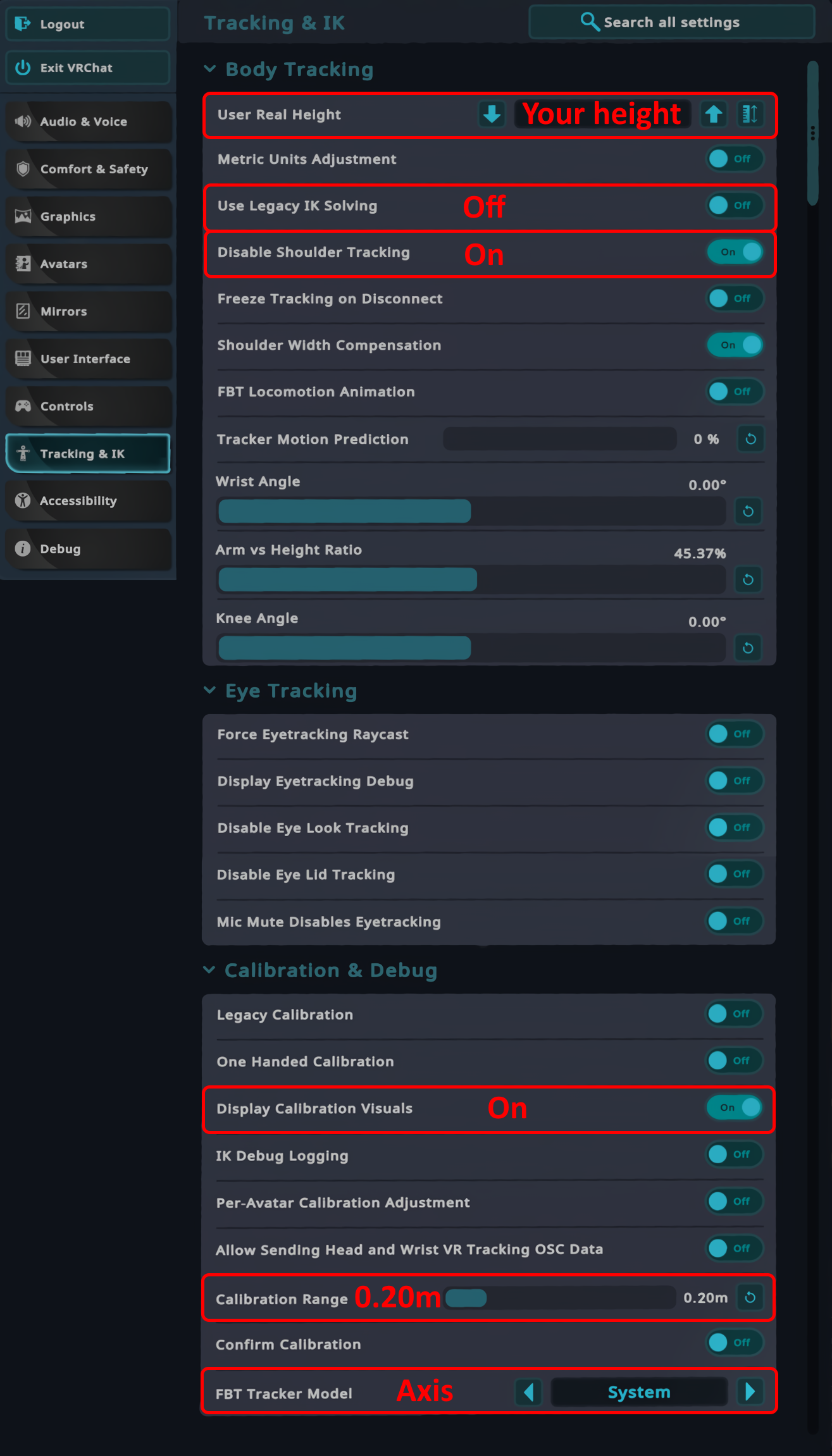
Mobile Setup
There are a couple options for using SlimeVR natively on mobile devices instead of on a PC. This guide will help you set up the SlimeVR server on a mobile device or Quest headset.
Android
Requirements
- Android 8.0+ (Oreo)
- Port 8080 is free
- App is set to run in the background (https://dontkillmyapp.com/)
Installation
Download the SlimeVR app from the Play Store to install it on Android
You can also download SlimeVR-android.apk from the latest SlimeVR release and install it, especially on devices without access to the Play Store. You may need to enable installing from unknown sources, generally your phone will prompt you for this.
Video guides
Phone setup
Quest setup
This setup is not recommended as the Quest OS is buggy with the SlimeVR app. This method should only be used as a last resort; running the app on a phone or PC (even if it isn't powerful enough for VR) will be a significantly better experience.
iOS
You can find the instructions to install SlimeVR on iOS in the #"iOS Beta Server" forum post on the SlimeVR Discord.
MacOS Installation
1. Download
Download the SlimeVR installation file for Mac (.dmg).
2. Install
Open the .dmg and drag SlimeVR app into Applications.
3. Open
Open SlimeVR from Applications. (You will get this error shown below)
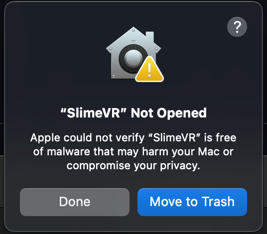
4. Security
Go to System Settings - > Privacy and Security -> You should see SlimeVR was blocked as shown below. Click "Open Anyway".
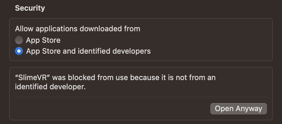
Installing Java
Download and install Java depending on what processor you have.
Allow trackers to connect to your Mac
Go to System Settings - > Privacy and Security -> Scroll to the bottom -> Security -> Allow accessories to connect: Change this to "Automatically When Unlocked".
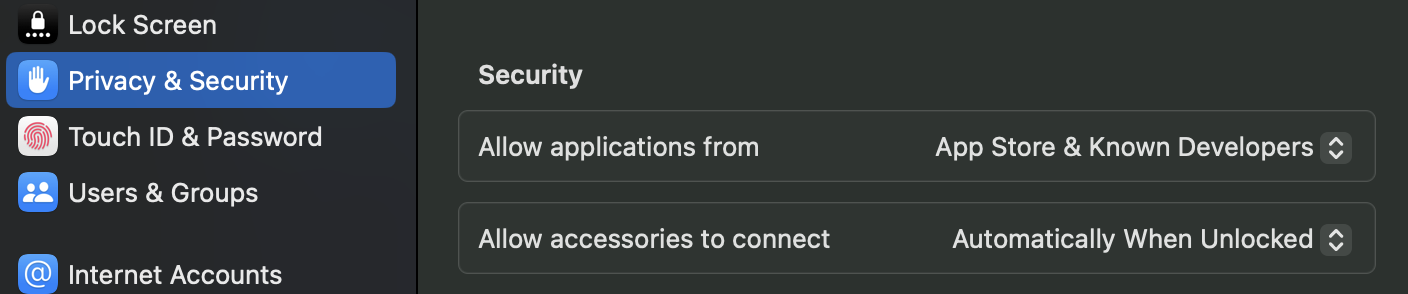
Allow network access
Open SlimeVR and follow the Setup Guide to connect a tracker. You may run into the below message. Click "Allow" to connect trackers.
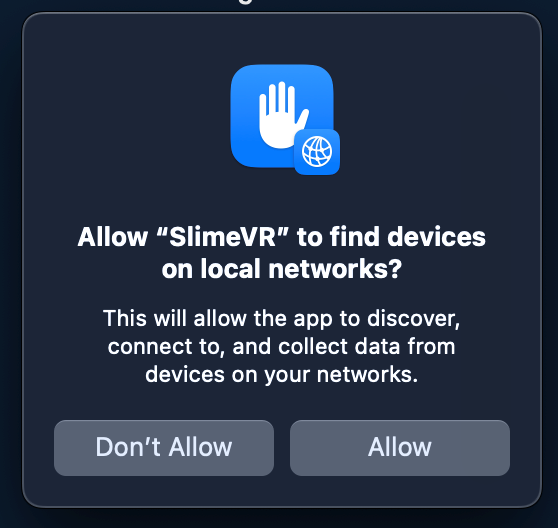
Created by Sigtyr, edited by Smeltie
Here is a list of the contributors who have helped improve the docs. They are the best of the best!
- calliePepper
- NWBx01
- deiteris
- adigyran
- lordbagel42
- Smeltie
- Eirenliel
- Erimelowo
- carl-anders
- ZRock35
- ButterscotchV
- nullstalgia
- Quantum-Red
- RedHawk989
- Disappear9
- TomYumVR
- ThreadOfFate
- sctanf
- Lupinixx
- Spazznyan
- Vyolex
- frosty6742
- TheDevMinerTV
- Rosdayle
- TheButlah
- AtlasThePro
- Uriel (ImUrX)
- Aoki (kruemmelbande)
- JovannMC
- Shine Bright
- Aed
- Meia
- Depact
- Amebun
- Nicolas R.
If you feel you're missing from this list, feel free to add yourself in a PR.
FCC COMPLIANCE
This equipment has been tested and found to comply with the limits for a Class B digital device, pursuant to part 15 of the FCC Rules. These limits are designed to provide reasonable protection against harmful interference in a residential installation. This equipment generates, uses and can radiate radio frequency energy and, if not installed and used in accordance with the instructions, may cause harmful interference to radio communications. However, there is no guarantee that interference will not occur in a particular installation. If this equipment does cause harmful interference to radio or television reception, which can be determined by turning the equipment off and on, the user is encouraged to try to correct the interference by one or more of the following measures:
- Reorient or relocate the receiving antenna.
- Increase the separation between the equipment and receiver.
- Connect the equipment into an outlet on a circuit different from that to which the receiver is connected.
- Consult the dealer or an experienced radio/TV technician for help.
Changes or modifications not expressly approved by the manufacturer could void your authority to operate the equipment.
IC COMPLIANCE
These devices comply with the Industry Canada License-exempt RSS Standard(s).
Operation is subject to the following 2 conditions: (1) These devices may not cause interference , and (2) These devices must accept any interference, including those that may cause undesired operation of the device.
Ces appareils conforment aux normes CNR exempts de license d'Industrie Canada.
L’opération est soumise aux 2 conditions suivantes : (1) Ces appareils ne doivent pas provoquer d'interférences, et (2) Ces appareils doivent accepter toute interférence, y compris celles susceptibles de provoquer une opération non désirée de l'appareil.
CE COMPLIANCE
SlimeVR hereby declares that these SlimeVR Trackers are compliant with the Requirements imposed by Directive 2014/53/EU (RED). This product is allowed to be used in all EU member states. Maximum radio frequency power transmitted in the frequency bands in which the trackers operate are less than the highest limit value specified in the related standard.
UKCA COMPLIANCE
SlimeVR hereby declares that these SlimeVR Trackers are compliant with the Requirements imposed by the Radio Equipment Regulations 2017. This product is allowed to be used in the United Kingdom. Maximum radio frequency power transmitted in the frequency bands in which the trackers operate are less than the highest limit value specified in the related standard.
RoHS & WEEE COMPLIANCE
RoHS: SlimeVR Trackers comply with the relevant provisions of the RoHS Directive for the European Union.
WEEE Directive: This symbol indicates that this product should not be disposed of with other household wastes within the EU. This to prevent possible harm to the environment or human health from uncontrolled waste disposal. Please recycle this product to promote sustainable reuse of the material resources.
Please contact the retailer where the product was purchased to return your used device to be recycled.
Privacy Policy
SlimeVR FBT Server for Android Privacy Policy
The app does not collect or retain any of your personal information. However, it sends some information to other systems in order to minimally function. No data is ever sent outside of your local network without your explicit command to do so.
The following data may be sent to the server of your choice when you establish a connection:
- Information received from extrnal sensor connected to the app, such as SlimeVR Trackers;
- Acceleration and rotation of your phone;
- Your phone's local IP address and other data that is required to send and receive network packets;
- Any other data you input in the settings of the app.
Additionally, the app contains an Auto Discover feature that seeks to automatically find and discover compatible servers and devices on your local network. It periodically broadcasts UDP packets to your entire local network when the app is open. These packets contain your phone's local IP address and other data that is required to send and receive UDP packets.
This privacy policy does not govern the use of your data by the servers you connect to. The aforementioned data is hence subject to the privacy policy of compatible servers on your local network, or on another network if you choose to enter another network's IP address.
SlimeVR Compatibility
We get a lot of questions about hardware compatibility, so we compiled a list of devices and software we know to be compatible. If your hardware is not on the list, there is a good chance it may still be compatible, but we recommend checking with our Discord.
Compatible Headsets by Brand
Oculus
| Headset | SteamVR | Standalone VRChat | Notes |
|---|---|---|---|
| Rift | Yes | No | |
| Rift S | Yes | No | |
| Quest 1 | Yes | No | |
| Quest 2 | Yes | Yes | |
| Quest 3 | Yes | Yes | |
| Quest 3S | Yes | Yes | |
| Quest Pro | Yes | Yes |
Valve
| Headset | SteamVR | Standalone VRChat | Notes |
|---|---|---|---|
| Index | Yes | No | |
| Steam Frame | Yes | Yes |
HTC
| Headset | SteamVR | Standalone VRChat | Notes |
|---|---|---|---|
| Vive | Yes | No | |
| Vive Pro | Yes | No | |
| Vive Pro Eye | Yes | No | |
| Vive Cosmos | Yes | No | |
| Vive Cosmos Elite | Yes | No | |
| Vive Pro 2 | Yes | No | |
| Vive Focus | Yes | No | |
| Vive Focus Plus | Yes | No | |
| Vive Focus 3 | Yes | No | |
| Vive XR Elite | Yes | Yes | |
| Vive Focus Vision | Yes | Yes |
Pico
| Headset | SteamVR | Standalone VRChat | Notes |
|---|---|---|---|
| Neo 2 | Yes | No | |
| Neo 2 Eye | Yes | No | |
| Neo 3 Pro | Yes | No | |
| Neo 3 Pro Eye | Yes | No | |
| Neo 3 Link | Yes | No | |
| Pico 4 | Yes | Yes | |
| Pico 4 Pro | Yes | Yes | |
| Pico 4 Enterprise | Yes | Yes* | Not available on Pico Store. Requires APK Installation (Standalone). |
| Pico 4 Ultra | Yes | Yes | |
| Pico 4 Ultra Enterprise | Yes | Yes* | Not available on Pico Store. Requires APK Installation (Standalone). |
BigScreen
| Headset | SteamVR | Standalone VRChat | Notes |
|---|---|---|---|
| Beyond 1 | Yes | No | |
| Beyond 2 | Yes | No |
Shiftall
| Headset | SteamVR | Standalone VRChat | Notes |
|---|---|---|---|
| MeganeX | Yes | No | |
| MeganeX Superlight | Yes | No | |
| MeganeX Superlight 8K | Yes | No | |
| MeganeX 8K Mark II | Yes | No |
Pimax
| Headset | SteamVR | Standalone VRChat | Notes |
|---|---|---|---|
| Pimax 4K | Yes | No | |
| Pimax 5K Plus | Yes | No | |
| Pimax 5K XR | Yes | No | |
| Pimax Vision 8KX | Yes | No | |
| Pimax Vision 8K+ | Yes | No | |
| Pimax Artisan | Yes | No | |
| Pimax 5K Super | Yes | No | |
| Pimax Crystal QLED | Yes | No | |
| Pimax Portal QLED View | Yes | No | |
| Pimax Portal View | Yes | No | |
| Pimax Crystal Light | Yes | No | |
| Pimax Crystal Super | Yes | No |
Sony
| Headset | SteamVR | Standalone VRChat | Notes |
|---|---|---|---|
| PlayStation VR | Yes | No | SteamVR Only |
| PS VR2 | Yes | No | SteamVR Only |
| Headset | SteamVR | Standalone VRChat | Notes |
|---|---|---|---|
| Cardboard | Yes | No | SteamVR Using iVRy or VRidge |
Samsung
| Headset | SteamVR | Standalone VRChat | Notes |
|---|---|---|---|
| Galaxy XR | Yes | No | |
| Odyssey Plus | Yes | No |
Apple
| Headset | SteamVR | Standalone VRChat | Notes |
|---|---|---|---|
| Vision Pro | Yes | No | Requires ALVR or other app |
Varjo
| Headset | SteamVR | Standalone VRChat | Notes |
|---|---|---|---|
| VR1 | Yes | No | |
| VR2 | Yes | No | |
| VR2 Pro | Yes | No | |
| XR1 | Yes | No | |
| VR3 | Yes | No | |
| XR3 | Yes | No | |
| Aero | Yes | No | |
| XR4 | Yes | No | |
| XR4 Focal Edition | Yes | No |
HP
| Headset | SteamVR | Standalone VRChat | Notes |
|---|---|---|---|
| Reverb | Yes | No | |
| Reverb G2 | Yes | No | |
| Reverb G2 Omnicept | Yes | No | |
| VR1000 | Yes | No |
Lenovo
| Headset | SteamVR | Standalone VRChat | Notes |
|---|---|---|---|
| Explorer | Yes | No | |
| Mirage Solo | Yes | No | Through iVRy |
| Legion VR700 | Yes | No | |
| ThinkReality VRX | Yes | No | Windows Mixed Reality |
Dell
| Headset | SteamVR | Standalone VRChat | Notes |
|---|---|---|---|
| Visor | Yes | No | Windows Mixed Reality |
Asus
| Headset | SteamVR | Standalone VRChat | Notes |
|---|---|---|---|
| HC102 | Yes | No | Windows Mixed Reality |
Compatible trackers or hardware
Many trackers from other vendors can be used natively with SlimeVR, through third-party apps, or via Fusion using SteamVR. Any SteamVR-tracked device can be used in SlimeVR through Fusion. Below is a list of common hardware and the methods used to integrate it with SlimeVR.
HTC
| Hardware | Method | Notes |
|---|---|---|
| Vive 1.0 | Fusion | |
| Vive 2.0 | Fusion | |
| Vive 3.0 | Fusion | |
| Vive Ultimate | Fusion |
Tundra
| Hardware | Method | Notes |
|---|---|---|
| Tundra Tracker | Fusion |
Sony
| Hardware | Method | Notes |
|---|---|---|
| Mocopi | Native or MoSlime | https://github.com/moslime/moslime |
| PS4 DualShock | Everything to IMU | https://github.com/Sebane1/Everything_To_IMU_SlimeVR |
| PS5 DualSense | Everything to IMU | https://github.com/Sebane1/Everything_To_IMU_SlimeVR |
Nintendo
More information about wrangler can be found here.
| Hardware | Method | Notes |
|---|---|---|
| Joycons | Wrangler | https://github.com/carl-anders/slimevr-wrangler |
| Wii Motes | Everything to IMU | https://github.com/Sebane1/Everything_To_IMU_SlimeVR |
| 2DS & 3DS (XL) | Everything to IMU | https://github.com/Sebane1/Everything_To_IMU_SlimeVR |
Shiftall
More information about wrangler can be found here.
| Hardware | Method | Notes |
|---|---|---|
| HaritoraX | SlimeTora | https://github.com/OCSYT/SlimeTora |
Rebocap
| Hardware | Method | Notes |
|---|---|---|
| Rebocap | ReboSlime | https://github.com/colasama/ReboSlime |
Axis
| Hardware | Method | Notes |
|---|---|---|
| Axis Trackers | AXSlime | https://github.com/CaiVR/AXSlime |
Somatic
| Hardware | Method | Notes |
|---|---|---|
| Orion Trackers | Native |
Fluxpose
| Hardware | Method | Notes |
|---|---|---|
| Fluxpose Tracker + Beacon | Fusion | Requires both components (headset tracker + beacon). |
Smartphones & Smartwatches
A lot of Smartphones and even some smartwatches can be used as additional SlimeVR trackers, you can find more information about OwOTrack here.
ShadowPC
ShadowPC can be used with SlimeVR! You can find more information here.
Compatible software and games
SlimeVR supports any SteamVR game that supports SteamVR full body tracking. Some popular options are:
- VRChat
- Chillout VR
- Resonite
- Blade & Sorcery
- Dance Dash
- Beat Saber (using mods)
- Zenith VR
- And more!
SlimeVR can also be used with VRChat on standalone headsets as listed above!
VR Tools and Estimation
Virtual Desktop Estimation
SlimeVR is compatible with and frequently used with Virtual Desktop Estimation, specifically for arms!
Quest Inside-Out Body Tracking
Quest IOBT is frequently used in conjunction with Virtual Desktop Estimation for arms!
OVR Advanced Settings
SlimeVR is fully compatible with OVR Advanced Settings and does not interfere.
Vtubing and Motion Capture
Blender
SlimeVR can be used with Blender using either VMC4B or by recording BVH files directly from our software! A great tutorial can be found here.
VNyan
VNyan can be used with SlimeVR using VMC! A great tutorial can be found here.
Warudo
Warudo can be used with SlimeVR using VMC! A great tutorial can be found here.
Unity
Unity can be used with SlimeVR using VMC! A great showcase can be found here.
Unreal Engine
Unreal Engine can be used with SlimeVR using VMC!
Godot
Godot can be used with SlimeVR using VMC and external tools/plugins!
StretchSense
StretchSense XR Game, XR Train, and XR Studio gloves are fully SlimeVR compatible through VMC and SteamVR!
Page by Smeltie, Amebun | Video guides by Zrock35, Kana Fuyuko