Smol Tracker Soldering
This page offers two ways to learn to solder your Smol Tracker: a video tutorial and a step-by-step text guide. Choose the method that works best for you!
Table of Contents
Lyall's Soldering Video Tutorial
If you prefer to watch a demonstration, you can follow along with the video below.
Depact's Soldering Text Tutorial
Tools Needed
Essential Tools
- Side cutter pliers
- Tweezers (used for holding buttons and header pins in place)
- Soldering iron
- Soldering sponge (used for cleaning the soldering iron tip)
- Flux-cored solder wire (recommended for ease of use over separate solder and flux)
- Scissors (used for cutting Kapton tape)
Optional Additional Tools
- Soldering jig (optional, but makes holding the board easier)
- Soldering mat (optional, protects your workspace)
Types of PCB Soldering Defects and Solutions
Visual guide for PCB soldering and identifying soldering defects and proper solder joints.
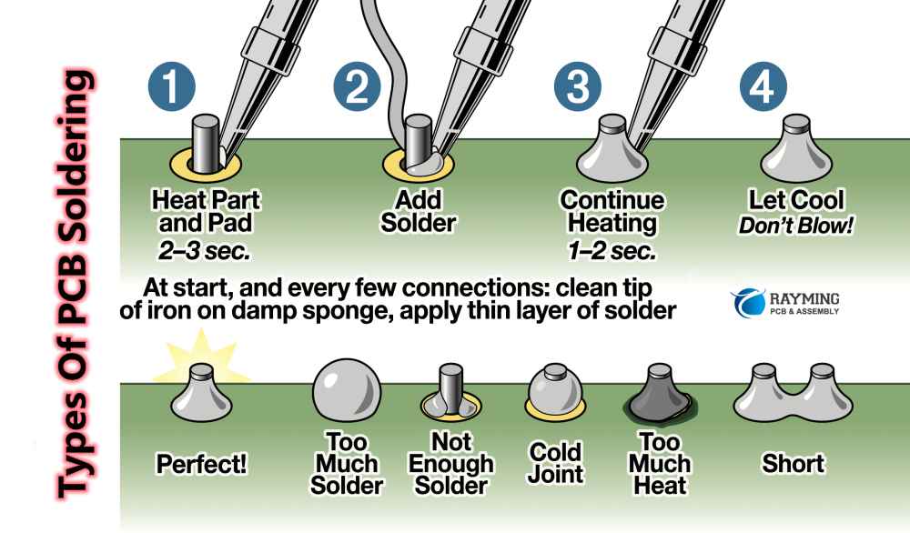
Image source: [RayPCB](https://www.raypcb.com/pcb-soldering/)
Soldering Steps
-
Solder the Button
- Prefill the through-holes under the button contacts with solder.
- Place the button onto the solder-filled holes.
- Heat the area with the soldering iron until the solder connects the button pads securely.

-
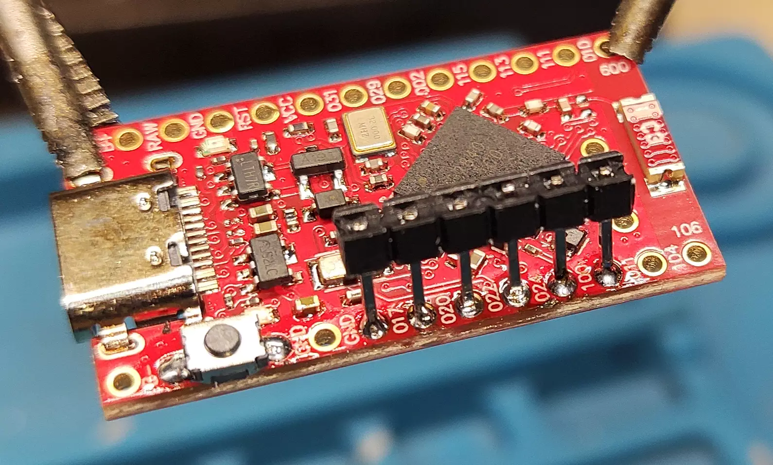
Solder the Breakaway Header
- Break off a segment of 6 pins from the breakaway header strip.
- Insert the header into the through-holes, leaning it slightly toward the center of the board to hold it in place.
- Solder each pin one by one, making sure they remain straight and securely attached.
-
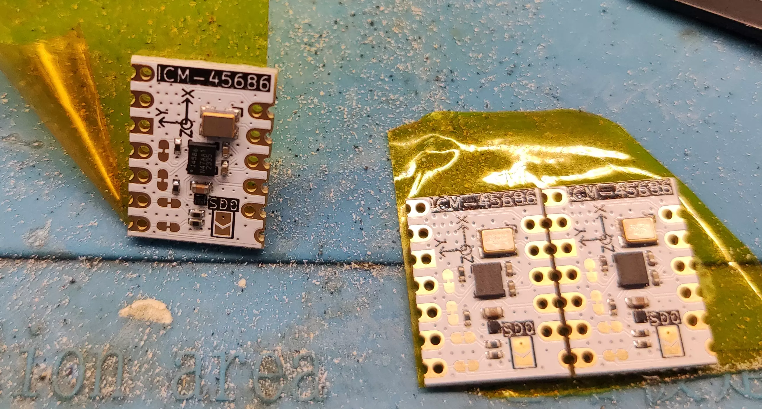
Insulate the IMU
- Cover the back of the IMU module with Kapton tape to prevent shorts.
- Cover the back of the IMU module with Kapton tape to prevent shorts.
-
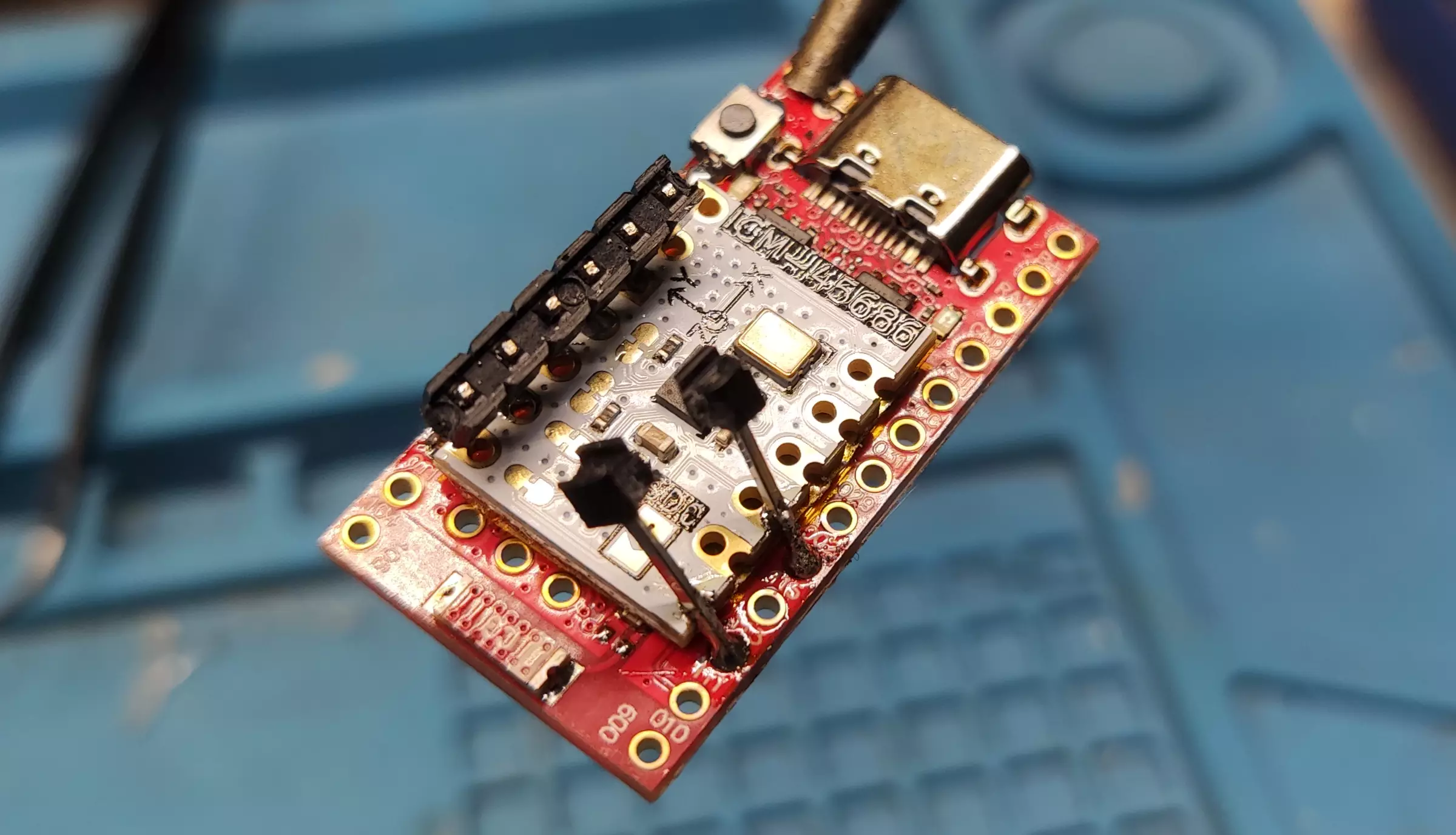
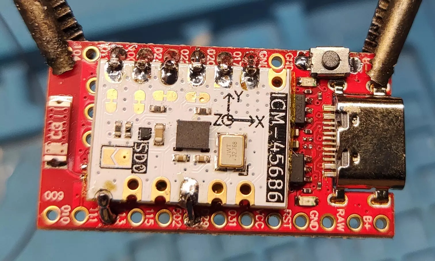
Solder Headers to the IMU
This tutorial shows how to solder the ICM-45686. For other IMUs, see Smol Tracker Schematics.
- Solder a row of breakaway headers to one side of the IMU.
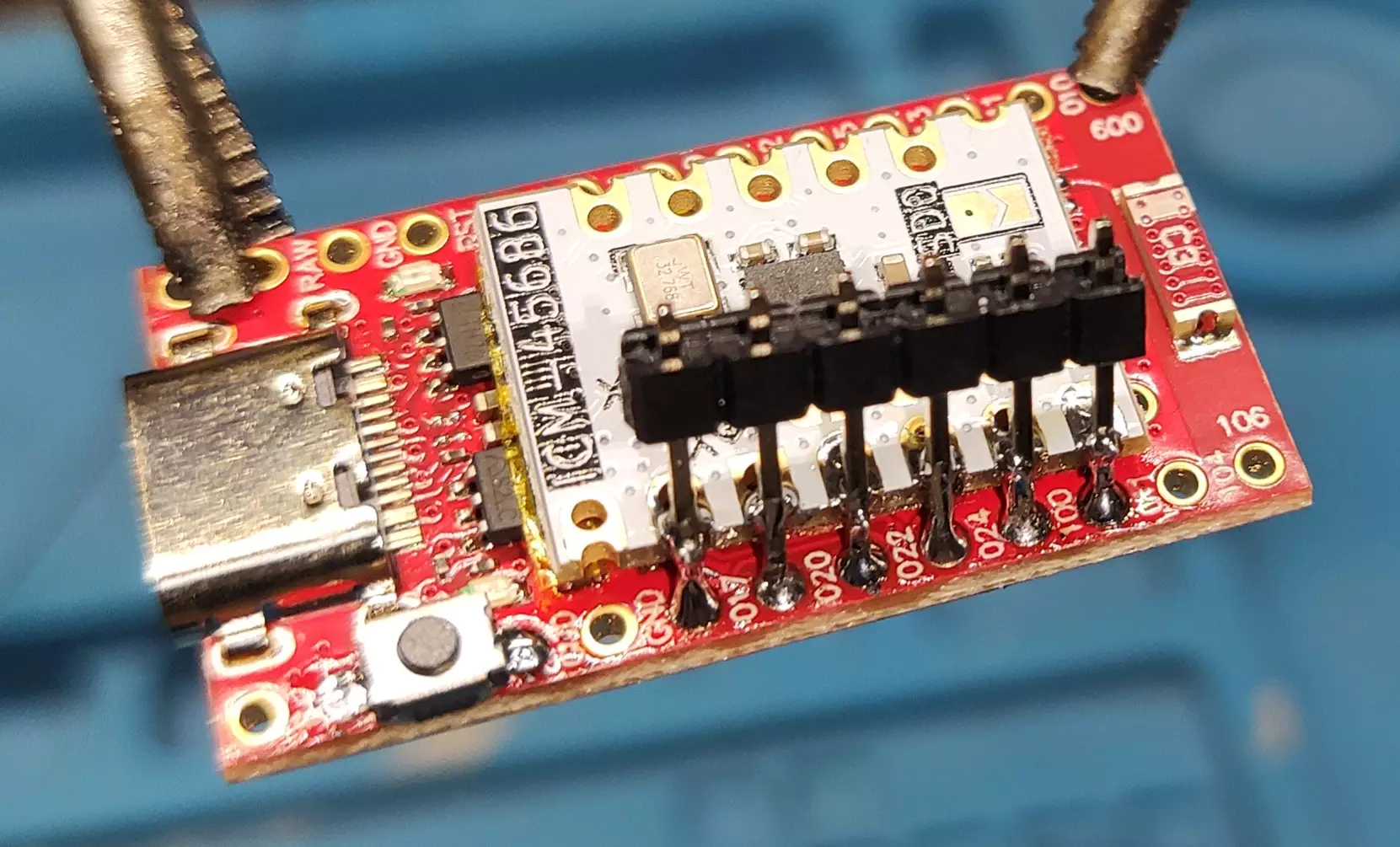
- Solder the headers on the other side at a slight angle so they make solid contact with the IMU pads.
-
Trim and Inspect Header Pins
- Use side cutter pliers to trim excess length from the header pins.
- Inspect the solder joints and add more solder if needed, but avoid overheating, as this can loosen the pins.
-
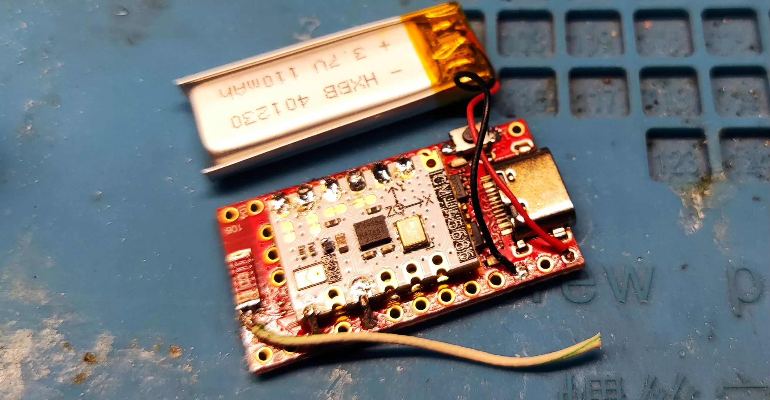
Solder the Antenna Mod and Battery
- Solder the antenna wire and the battery leads to their respective pads.
- For optimal performance, the antenna wire should be cut to 31.2 mm. Any deviation will reduce performance.
Double-check each connection carefully before powering the board.
Use the info command in a serial terminal to check if the IMU is detected. If it is not detected, this usually means there is a soldering issue, or less commonly, a hardware fault.
Additional Materials
Ibis Soldering Fixture
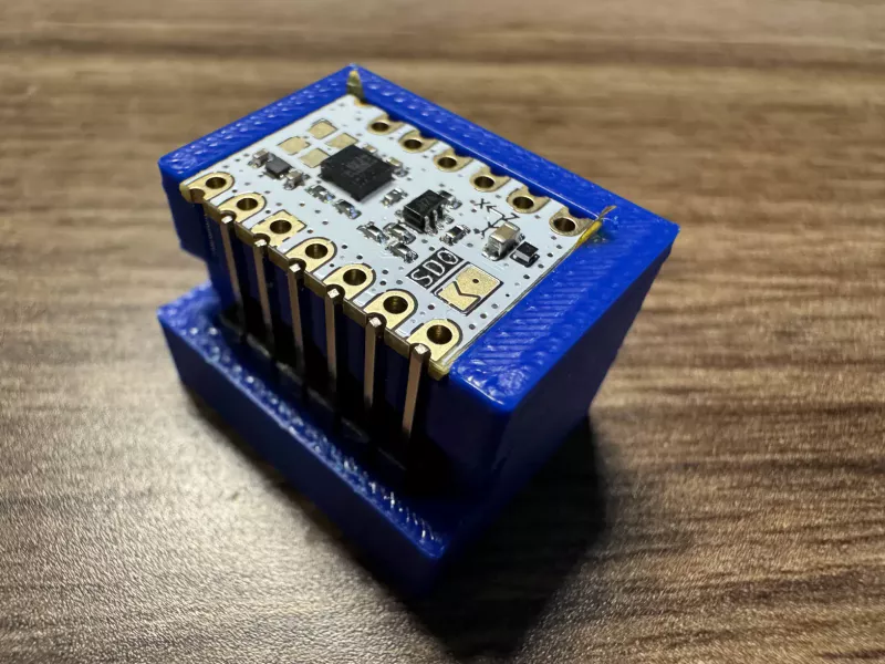
You can optionally use the Ibis soldering fixture to hold your IMU and headers securely in place while soldering. Note: That this fixture does not work for every IMU, as it is specifically designed for the LSM6DSR/LSM6DSV from Deyta's Moffshop and ICM-45686 from SlimeVR Store.
Created by Shine Bright ✨ and Depact