Tracker Schematics
SPI is the preferred protocol due to its better performance and energy efficiency. As a result, I2C may eventually be phased out and might not be supported in future firmware updates. Note that the magnetometer is not yet available over SPI.
Wemos D1 Mini
- IMUs ranked from best - worst
- - Currently the best widely available IMU and cheaper than LSM6DSV.
- - Very good and slightly cheaper than BNO085.
- - Decent and a little cheaper than ICM-45686 and LSM6DSV. Experimental.
- - Very good, but expensive $$$. Not recommended.
- - Adafruit version of BNO085. Not recommended.
- - Performs slightly better than BMI160. Still terrible. DO NOT USE!
- - Very cheap, and with equally low performance. DO NOT USE!
- - Cheap and worse than BMI160. DO NOT USE!
- - Worse than BMI270 and plagued with fakes. DO NOT USE!
- - Experimental cheaper MPU9250 equivalent. DO NOT USE!
- - Allows for a second motion sensor to be connected.
- - The device is able to sense the battery life remaining using a 180k resistor.
- - Allows for usage even when charging, and is a recommended safety measure.
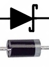 Note: If you are using the charge diodes the grey band goes on the side represented by the tip of the arrows in the diagram above.
| Label | GPIO | Input | Output | Description |
|---|---|---|---|---|
| A0 | ADC0 | Analog Input | No | For analog input from 0 to 3.3v and no output. |
| RX | GPIO3 | Yes | RX pin only | High at Boot. |
| TX | GPIO1 | Tx pin only | Yes | High at Boot. |
| D0 | GPIO16 | No interrupt | No I2C, PWM | Used to wake up chip from deep sleep, High at Boot. |
| D1 | GPIO5 | Yes | Yes | Often used as SCL |
| D2 | GPIO4 | Yes | Yes | Often used as SDA |
| D3 | GPIO0 | Pulled up | Yes | Connected to Flash button |
| D4 | GPIO2 | Pulled up | Yes | Connected to built-in LED, High at Boot. |
| D5 | GPIO14 | Yes | Yes | SCLK pin for SPI interface |
| D6 | GPIO12 | Yes | Yes | MISO pin for SPI interface |
| D7 | GPIO13 | Yes | Yes | MOSI pin for SPI interface |
| D8 | GPIO15 | Pulled to ground | Yes | CS pin for SPI interface |
Cable layout recommendation for auxiliary tracker
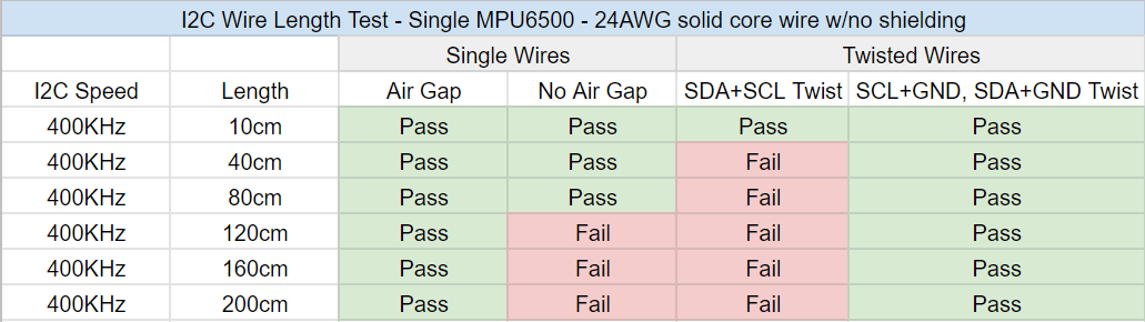
Note that while schematics show SDA and SCL running adjacent to each other, make sure that they are not physically adjacent when running in the auxiliary tracker cable. This is to avoid crosstalk and ensure stable operation of both trackers when cabled and allow the extension to safely reach more than 80cm.
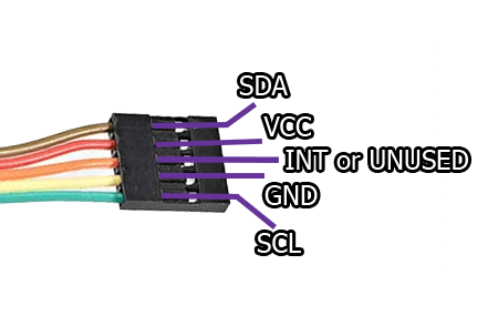
If you are using a ribbon cable or similar layout, use the following cable layout as a reference:
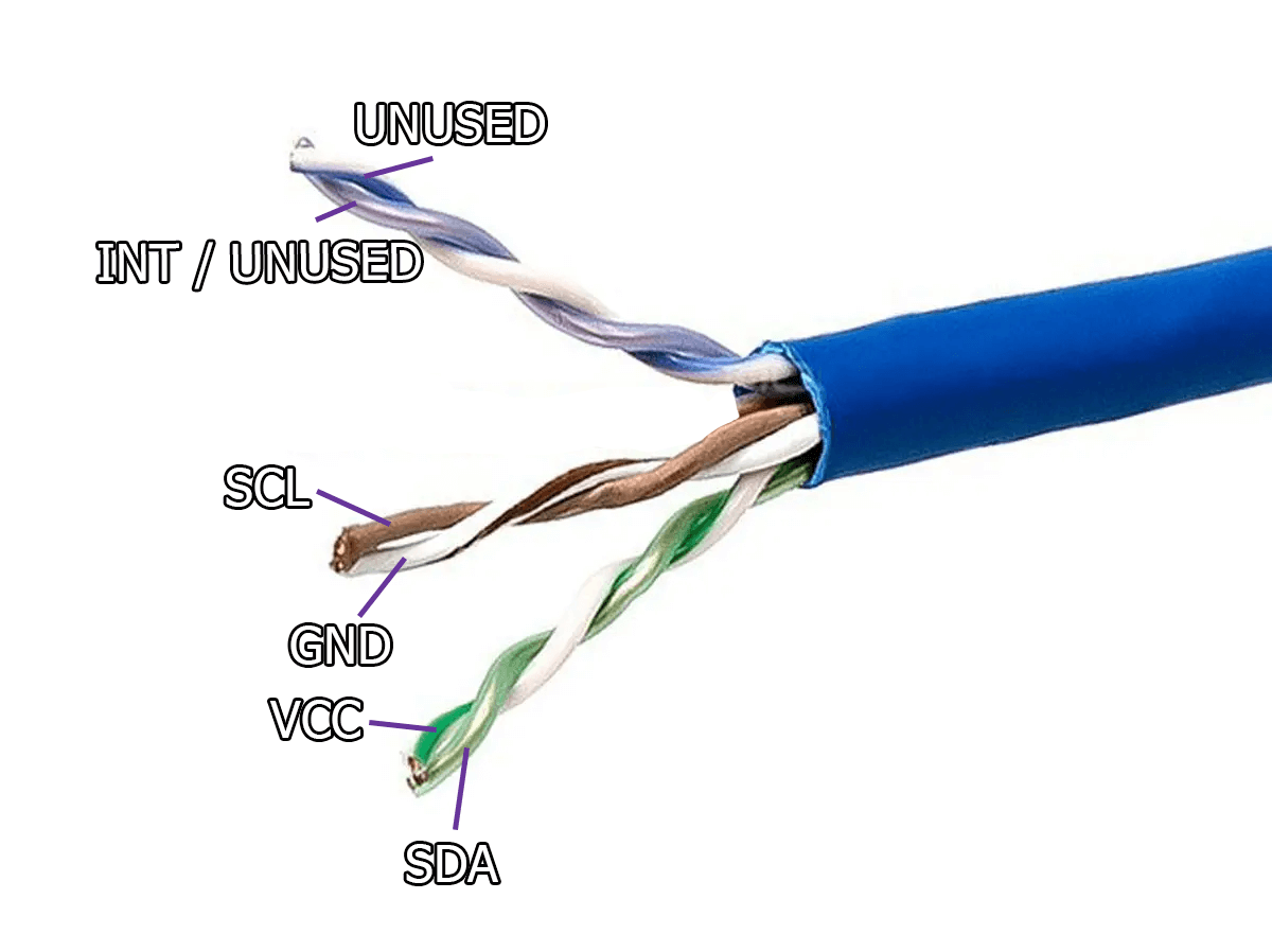
If you are using a twisted pair cable or similar layout, use the following cable layout as a reference:
Code put together by Carl (https://github.com/carl-anders), with images made by Lune#0241, nwbx01, Meia, Aed and Reclusious#2022 thanks to the help of the whole DIY community. Doc page integration by emojikage. Edited by calliepepper, Aed, and Amebun. Thanks to snapchat_hotdog for the testing on the extension lengths.