Official DIY Clone Trackers
Due to the nature of SlimeVR being open-source it is entirely possible to create your own trackers based on the official design files. Especially now that the SlimeVR Store started selling components such as: cases, cables and IMUs!
- SlimeVR Store
- Where to find the production files
- How to order SlimeVR PCBs from a manufacturer
- Soldering the IMU to the main PCB
- Flashing the firmware
- Final Assembly
SlimeVR Store
Since a little while now there is an official SlimeVR Store! Here you can buy replacement cases, cables and even BNO modules!
Where to find the production files
You can find the production files for both the main tracker, extension boards and the BNO module here: Main Tracker Board, Extension Board and BNO Module. Or the latest revision that doesn't use IMU Modules: Main Tracker R14. These will link you to the respective OSHWLab pages, here you can download the files or directly open them in the online version of EasyEDA.
How to order SlimeVR PCBs from a manufacturer
When you open either of the two links provided above, you will find yourself on the OSHWLab website. From there, you can select "Open in Editor" to access the files in EasyEDA. You do not have to download any software for this process since EasyEDA can run in your browser! Opening the files in EasyEDA allows you to view, edit, or make adjustments if necessary for your specific use case (though this is not required for official clone trackers). Next, navigate to the top bar in EasyEDA, and under "Fabrication," click on "PCB Fabrication file (gerber)." Then, click "no" on both options, as EasyEDA has not been configured yet, and the files are already prepared. From here you can do a one click order. You should be able to leave all the settings as is aside from Surface Finish, set this to LeadFree HASL or ENIG! You can also change the color of the solder mask if you so desire. After this you should be able to continue with the ordering process and then the wait begins!
BEWARE Sometimes when you get redirected to JLCPCB it won't fully load, in this case you might have to try again.
Soldering the IMU to the main PCB
The soldering process for official slimes is a little different than your usual DIY slimes. Where normally DIY slimes are soldered together with through hole wiring, SlimeVR on the other hand uses castelated edges. This makes soldering the IMU very fast and efficient.
What do you need to solder the IMU to the main PCB?
- Soldering iron.
- Leadfree Solder.
- Chisel style soldering tip (optional but recommended).
- Assembly jig (optional).
Instructions:
Place the IMU module on top of the main tracker PCB as shown below.
![]() Now solder the 6 castelated edges to the main board as shown in the picture above.
Using a chisel tip makes this process significantly faster and easier.
For more soldering tips you can check out this video:
Now solder the 6 castelated edges to the main board as shown in the picture above.
Using a chisel tip makes this process significantly faster and easier.
For more soldering tips you can check out this video:
Flashing the firmware
To flash the firmware you will need:
- USB-C cable with data pins (official SlimeVR cable is recommended).
- Paperclip or tweezers to bridge a connection on the PCB.
Flashing the firmware for these official trackers is practically identical to the process of flashing DIY trackers.
A link to the online flasher with all the settings pre-configured can be found here.
If the link does not work or the settings don't show up right after clicking you can find the manual settings a little further down in this section.
As opposed to DIY trackers the official trackers need to be started in flash mode. You can do this by bridging the pads on the top side of the PCB as show below:
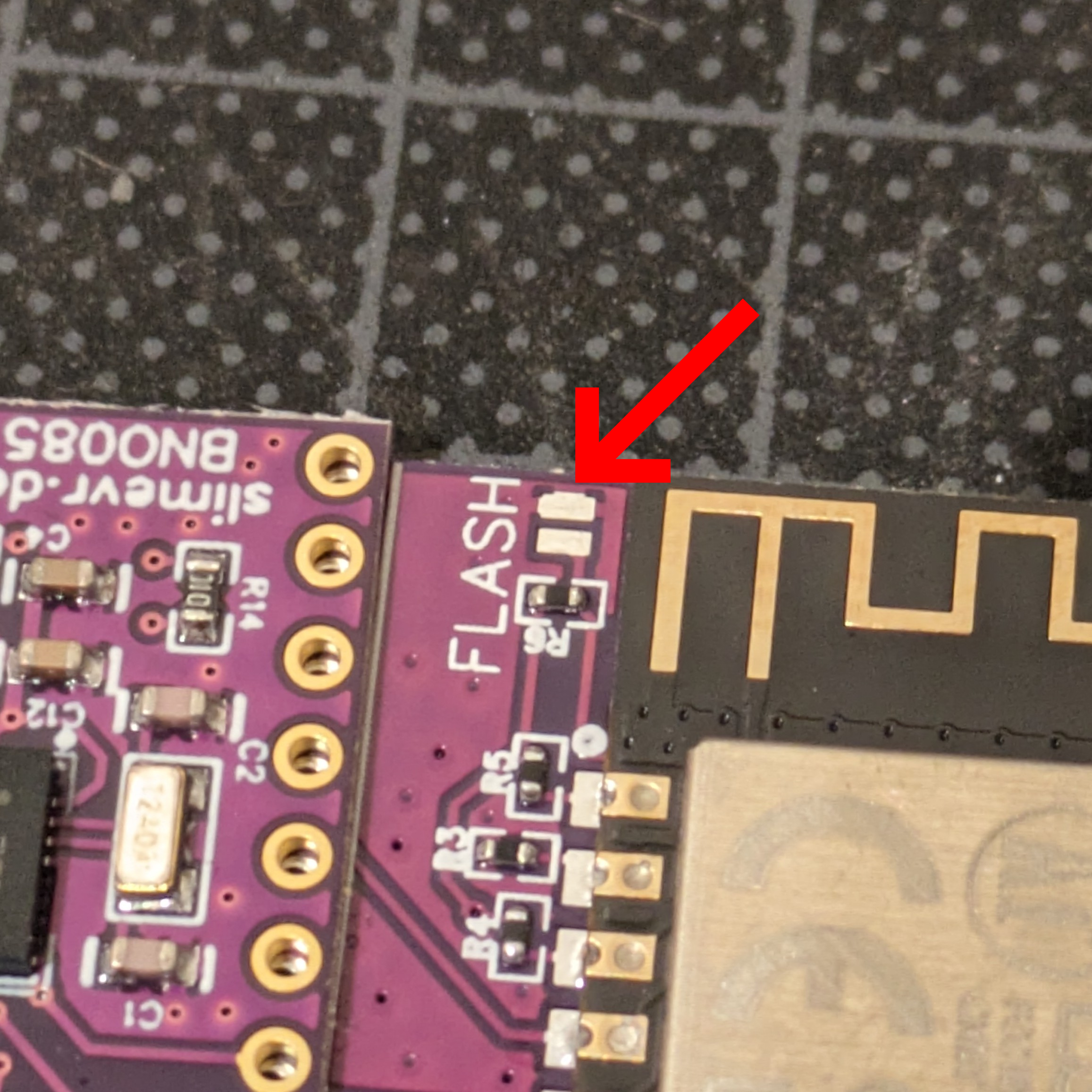 To enter flash mode, turn the tracker's power switch on by switching it to the right, connect the USB cable to the PC, now connect the USB cable to the PCB whilst bridging the exposed flash pads!.
The tracker should now have started in flash mode and be accepting of firmware.
Manual Flashing settings
As stated in defines.h the pins for the official PCB are:- SDA 14
- SCL 12
- INT 16
- INT_2 13
- Battery_Level 17
- LED_PIN 2
- LED_Inverted True
IMU Rotation should be set at 270 for both in case of the official setup using the BNO085.
Final Assembly
For final assembly we would like to refer to the official SlimeVR repair guide. This contains information regarding both assembly and disassembly. On an additional note, the sticky foam pad usually sits on the printed side of the battery (in the case of production units).
Written Assembly Guide
| Amount | Part |
|---|---|
| 1x | Case Top |
| 1x | Case Bottom |
| 2x | M2.5x10 Screw or M2.5x12 |
| 1x | PCB |
| 1x | Battery |
| 1x | Foam Pad |
| 1x | Sticker |
Attach a foam pad to the center of the battery (text side). Attach battery cable to the PCB. Turn on the tracker by sliding the switch to the right, make sure the blue light blinks continuously. Turn off the tracker by sliding the switch to the left! Place the PCB with the components facing down into the top case(make sure to insert at an angle, the ports are aligned and it sits flush). Place the battery with the foam side against the PCB, making sure the cable gets tucked under the battery. Place the bottom case halve on the assembled top halve. Screw the m3 screws into the cases to securely close it up, be careful not to pinch the battery cable! Place the sticker on the back.
Created by Smeltie